
Mesh.SetVerts
void SetVerts(T[] vertices, bool calculateBounds)
Assigns vertices with a custom vertex format to this Mesh! The format is derived from T’s fields, each of which must be tagged with a [VertComponent] attribute describing what it is. The shader this Mesh is drawn with must be one that works with the components this format provides, StereoKit’s built-in shaders all expect position, normal, texcoord and color.
A T that doesn’t exactly describe its own memory layout will throw an ArgumentException here, see [VertComponent] docs for the rules.
| T[] vertices | An array of vertices to add to the mesh. |
| bool calculateBounds | If true, this will also update the Mesh’s bounds based on the vertices provided. This requires the format to contain a float3 position component. |
Examples
Procedurally generating a wavy grid
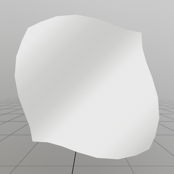
Here, we’ll generate a grid mesh using Mesh.SetVerts and Mesh.SetInds! This is a common example of creating a grid using code, we’re using a sin wave to make it more visually interesting, but you could also substitute this for something like sampling a heightmap, or a more interesting mathematical formula!
Note: x+y*gridSize is the formula for 2D (x,y) access of a 1D array that represents a grid.
const int   gridSize = 8;
const float gridMaxF = gridSize-1;
Vertex[] verts = new Vertex[gridSize*gridSize];
uint  [] inds  = new uint  [gridSize*gridSize*6];

for (int y = 0; y < gridSize; y++) {
for (int x = 0; x < gridSize; x++) {
	// Create a vertex on a grid, centered about the origin. The dimensions extends
	// from -0.5 to +0.5 on the X and Z axes. The Y value is then sampled from
	// a sin wave using the x and y values.
	//
	// The normal of the vertex is then calculated from the derivative of the Y
	// value!
	verts[x+y*gridSize] = new Vertex(
		new Vec3(
			x/gridMaxF-0.5f,
			SKMath.Sin((x+y) * 0.7f)*0.1f,
			y/gridMaxF-0.5f),
		new Vec3(
			-SKMath.Cos((x+y) * 0.7f),
			1,
			-SKMath.Cos((x+y) * 0.7f)).Normalized,
		new Vec2(
			x / gridMaxF,
			y / gridMaxF));

	// Create triangle face indices from the current vertex, and the vertices
	// on the next row and column! Since there is no 'next' row and column on
	// the last row and column, we guard this with a check for size-1.
	if (x<gridSize-1 && y<gridSize-1)
	{
		int ind = (x+y*gridSize)*6;
		inds[ind  ] = (uint)((x+1)+(y+1)*gridSize);
		inds[ind+1] = (uint)((x+1)+(y  )*gridSize);
		inds[ind+2] = (uint)((x  )+(y+1)*gridSize);

		inds[ind+3] = (uint)((x  )+(y+1)*gridSize);
		inds[ind+4] = (uint)((x+1)+(y  )*gridSize);
		inds[ind+5] = (uint)((x  )+(y  )*gridSize);
	}
} }
demoProcMesh = new Mesh(verts, inds);
Custom vertex formats
Meshes can use custom vertex layouts! Define a struct that provides what your shader’s vertex stage needs, and tag each field with a VertComponent attribute saying what it is. StereoKit derives the vertex format from the struct automatically. Since vertex data is matched to shader inputs by semantic, fields don’t need to be in the same order as the shader declares them!
[StructLayout(LayoutKind.Sequential, Pack = 1)]
struct VertPosColor
{
	[VertComponent(VertSemantic.Color,    VertFmt.U8Normalized, 4)]
	public Color32 color;
	[VertComponent(VertSemantic.Position, VertFmt.F32,          3)]
	public Vec3    pos;

	public VertPosColor(Vec3 position, Color32 c) { pos = position; color = c; }
}

Mesh     _mesh;
Material _material;

Mesh BuildOctahedron(float s)
{
	Mesh mesh = new Mesh();
	mesh.SetVerts(new VertPosColor[] {
		new VertPosColor(V.XYZ( s, 0, 0), new Color32(255,  0,  0,255)),
		new VertPosColor(V.XYZ(-s, 0, 0), new Color32(  0,255,  0,255)),
		new VertPosColor(V.XYZ( 0, s, 0), new Color32(  0,  0,255,255)),
		new VertPosColor(V.XYZ( 0,-s, 0), new Color32(255,255,  0,255)),
		new VertPosColor(V.XYZ( 0, 0, s), new Color32(  0,255,255,255)),
		new VertPosColor(V.XYZ( 0, 0,-s), new Color32(255,  0,255,255)) });
	mesh.SetInds(new uint[] {
		2,4,0,  2,0,5,  2,5,1,  2,1,4,
		3,0,4,  3,5,0,  3,1,5,  3,4,1 });
	return mesh;
}
Found an issue with these docs, or have some additional questions? Create an Issue on Github!