
StereoKit — Guides & Examples
StereoKit — Guides & Examples
StereoKit is a lightweight, low-dependency C# library for XR apps and games built on OpenXR. This file is part of a 2-file AI-friendly documentation set:
- StereoKit-docs-API.md — condensed API reference for every type — signatures, summaries, parameters
- StereoKit-docs-reference.md — conceptual guides and runnable C# code examples, one section per API member (this file) Source: https://stereokit.net/preview (generated from StereoKit’s XML doc comments)
Guides
Getting Started
Getting Started with StereoKit
The minimum prerequisite for StereoKit is the .NET SDK! You can use dotnet --version to check if this is already present.
If it is not, open up your Terminal, and run the following:
winget install Microsoft.DotNet.SDK.9
# Restart the Terminal to refresh your Path variable
On Linux, most distros have the .NET SDK in their package manager. You can find a [more complete list here] (https://learn.microsoft.com/en-us/dotnet/core/install/linux).
# Ubuntu
sudo apt-get install dotnet-sdk-9.0
# Debian
sudo dnf install dotnet-sdk-9.0

# On Ubuntu 24.04 or earlier, you need dotnet/backports
sudo add-apt-repository ppa:dotnet / backports`
With the .NET SDK installed, setting up a StereoKit project is quite simple!
# Install the StereoKit templates!
dotnet new install StereoKit.Templates

# Create a multiplatform StereoKit project, and run it
mkdir SKProjectName
cd    SKProjectName

dotnet new sk-multi
dotnet run

# For hot-reloading code, try this instead of `run`
dotnet watch
Native code developers can check out this guide for using StereoKit from C/C++.
Tools and IDEs
Once you’ve installed the templates via dotnet new install StereoKit.Templates,
you have your choice of tools! Visual Studio 2022 will recognize the
StereoKit templates when creating a new project, and the Command Line
workflow works well with VS Code and other editors.
- Get Visual Studio 2022 here.
- Or get VS Code here.
StereoKit is OpenXR based, so will work in any environment that supports OpenXR! On PC, this means you’ll want a desktop runtime such as SteamVR, Quest + Link, or Monado. If no OpenXR runtime is found, StereoKit will provide a nice Simulator that’s great for development! Some runtimes also provide a simulator for their platform, such as the Meta XR Simulator, so you can test their runtime without a headset.
Android
When using StereoKit’s sk-multi (multiplatform) template, deploying to an
Android device is pretty straightforward! From Visual Studio 2022, you’ll
need to set the SKProjectName.Android sub-project as your Startup Project
(Solution Explorer->Right click on SKProjectName.Android->Set as Startup
Project), and then you’ll have the option to deploy to any Android device
connected to your machine.
From the command line, or VS Code, you have to run the Android flavored .csproj explicitly.
# From the same folder as above
dotnet run --project .\Projects\Android\SKProjectName.Android.csproj
Minimum “Hello Cube” Application
The template does provide some code to help provide new developers a base to work from, but what parts of the code are really necessary? We can boil “Hello Cube” down to something far simpler if we want to! This is the simplest possible StereoKit application:
using StereoKit;

SK.Initialize();
SK.Run(() => {
	Mesh.Cube.Draw(Material.Default, Matrix.S(0.1f));
});
Next Steps
Awesome! That’s pretty great, but what next? Why don’t we build some UI? Alternatively, you can check out the StereoKit Ink repository, which contains an XR ink-painting application written in about 220 lines of code! It’s well commented, and is a good example to pick through.
For additional learning resources, you can check out the SDK source, which does contain a number of small demo scenes that are excellent reference for a variety of different StereoKit features! You can also check out the Learning Resources page for a couple of repositories and links that may help you out.
And don’t forget to peek in the API docs here! Most pages contain sample code that illustrates how a particular function or property is used in-context. The ultimate goal is to have a sample for 100% of the docs, so if you’re looking for one and it isn’t there, use the ‘Create an Issue’ link at the bottom of the web page to get it prioritized!
Getting Started Native
Getting Started with StereoKit - Native Code
StereoKit’s golden path is through C#, but the core of StereoKit is really just a C compatible library! C# is just a 1st class binding to this C library, so all of SK’s core functionality is still accessible from native code. This can be fantastic if you need the reliability of native code, or the ability to easily interact with other native libraries.
However! StereoKit’s core documentation is entirely focused on C#. Many C# docs map 1:1 with the C code, so this is still the best reference, but the C API is really only recommended to more advanced developers.
Native Template
The recommended way to get started with developing native StereoKit applications is via the CMake Template. Please see the template repository for up-to-date details and instructions! This template is excellent for Linux and Windows development, and can be fairly straightforward to use from VS Code.
Sample Code
StereoKit’s C API can be found in 2 different .h files, stereokit.h for all the main functions, and stereokit_ui.h for the user interface.
There is also some sample code available in the StereoKitCTest project that can be used for reference! It’s not as complete as the C# samples, but should help point you in the right direction for usage patterns and translation from C# docs.
Other Languages
Since StereoKit is a C API, it’s pretty easy to bind to other languages! While there are no official bindings other than C#, there are some partial examples for Zig and V, as well as a community driven effort to bind with rust!
Getting Started VS Code
Getting Started with StereoKit - Visual Studio Code
The regular getting started guide and the official templates now cater to Visual Studio Code, but if you’re interested in setting up a StereoKit project for VS without using the templates, here’s a quick rundown!
This guide also serves as a way to get started with C# projects in a command line environment! VS Code may have additional extensions that can make this experience simpler.
This requires having the .NET SDK
installed on your machine. Some development setups may already have this
installed, you can try running dotnet --version to double check!
To create the project:
mkdir ProjectName
cd ProjectName

dotnet new console
dotnet add package StereoKit
Add some code to get started:
using StereoKit;

SK.Initialize();
SK.Run(()=>{
    Mesh.Sphere.Draw(Material.Default, Matrix.S(0.1f));
});
To run the project:
# For .NET's hot-reload functionality
dotnet watch

# Or just a normal run
dotnet run
Learning Resources
Learning Resources
Outside of the resources here on the StereoKit site, there’s a number of other places you can go for learning information! Here’s a collection of external learning and sample resources to get you off the ground a little faster! If you have your own resources that you’d like to see linked here, just let us know!
Official Sample Projects
StereoKit Ink

A well documented repository that illustrates creating a complete but simplified inking application. It includes functionality like custom and standard UI, line rendering, file save/load, and hand menus.
Bing Maps API and Terrain Sample

A well documented repository showing how to load and display satellite imagery and elevation information from the Bing Maps API. It includes creating a terrain system using StereoKit’s shader API, loading color and height data from an external API, and building a pedestal interface to interact with the content.
Release Notes Demo for v0.3.1
This is an interactive release notes demo project that showcases the features released in StereoKit v0.3.1! Not every release has a demo like this, but it can be pretty enlightening to browse through a code-base such as this one for reference.
Light Baking and Scene Management
This is a quick demo for performantly managing static scenes, and baking lighting into them with StereoKit! This bakes lighting into the vertex colors of the mesh, so is visually limited by the number of vertices the mesh has, and will merge meshes together.
StereoKit Demos
These are the demos that test StereoKit features and APIs! They are occasionally documented, but frequently short and concise. They can be great to check out for a focused example of certain parts of the API!
Community Projects
Nakamir - Azure Active Directory Auth
This repo contains a StereoKit sample application (for Microsoft HoloLens 2) that demonstrates user authentication using Microsoft Azure Active Directory.
brunoshine - Azure Spatial Anchors
This is a demo application on how to use Azure Spatial Anchors with StereoKit to persist world anchors between sessions and devices.
Marc Plogas - Azure Spatial Anchors
Another ASA demo from Microsoft Cloud Advocate, Mark Plogas.
Nakamir and ClonedPuppy - Rigged Hands
Attaching a skinned mesh/model to StereoKit’s hand joint data.
Sites and Places
GitHub Discussions/Issues
The best place to ask a question! It’s asynchronous, and a great place for long-form answers that can also benefit others. The Discussions tab is best for questions, feedback, and more nebulous stuff, and the Issues tab is best if you think something might be misbehaving or missing!
The StereoKit Discord Channel
In a rush with a question, got a project to share, or just want to hang out and chat? Or maybe you’re looking for some feedback on a potential contribution? Whatever the case, come and say hi on the Discord! This is the core hang-out spot for the team and community :)
User Interface
Building UI in StereoKit
StereoKit uses an immediate mode UI system. Basically, you define the UI every single frame you want to see it! Sounds a little odd at first, but it does have some pretty tremendous advantages. Since very little state is actually stored, you can add, remove, and change your UI elements with trivial and standard code structures! You’ll find that you often have much less UI code, with far fewer places for things to go wrong.
The goal for this UI API is to get you up and running as fast as possible with a working UI! This does mean trading some design flexibility for API simplicity, but we also strive to retain configurability for those that need a little extra.
Making a Window
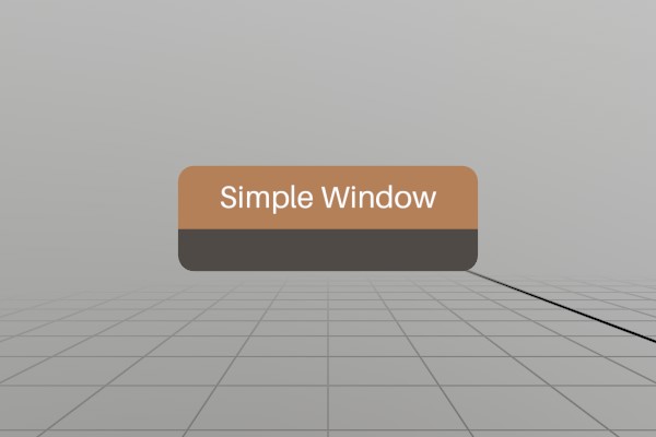
Lets start with a function that draws a simple, empty window.
void SimpleWindow(ref Pose windowPose)
{
	UI.WindowBegin("Simple Window", ref windowPose);

	UI.WindowEnd();
}
Looks pretty easy! You can begin a window, and end a window, and all
the UI elements between those two calls “belong” to that window. But
first, lets put this in context! StereoKit’s UI code must be called
every frame, so you would need to call SimpleWindow in your
application’s Step phase.
using StereoKit;

SK.Initialize();

Pose simpleWinPose = new (0, 0, -0.5f, Quat.LookDir(-Vec3.Forward));

SK.Run(()=> {
	SimpleWindow(ref simpleWinPose);
});
Note here that you own the Window’s Pose data, you can change it and
manage it however you want! StereoKit does take a reference to the
variable so it can update it based on the user’s current interaction
with the window, but that all happens immediately in the WindowBegin
function call, the reference doesn’t persist internally!
You might also have wondered about the Pose we used here! When the app starts up, the user will generally be at the “identity pose”, that is to say, at XYZ 0,0,0 facing forward 0,0,-1. For the window pose to be nice to a starting user, we put it half a meter forward, and have the window face backward towards the user’s starting point.
Making a Button
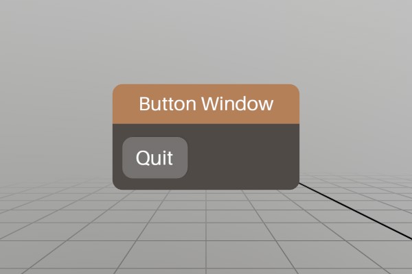
The simplest UI element, the button, illustrates nicely how “events”
occur in an immediate mode GUI system. Instead of some form of callback
or event, the Button function merely returns true on the first moment
it is pressed! You can safely put your function in an if statement,
and react to the interaction inline! Or pass execution along to a
callback, you do you.
void ButtonWindow(ref Pose windowPose)
{
	UI.WindowBegin("Button Window", ref windowPose);

	if (UI.Button("Quit"))
		SK.Quit();

	UI.WindowEnd();
}
Adding an image to a button is pretty easy too, UI.ButtonImg takes a
sprite and an optional layout to make your buttons a little snazzier!
Here we’re using one of StereoKit’s built-in default sprites, but you
can swap that out with a Sprite you’ve loaded from file too!
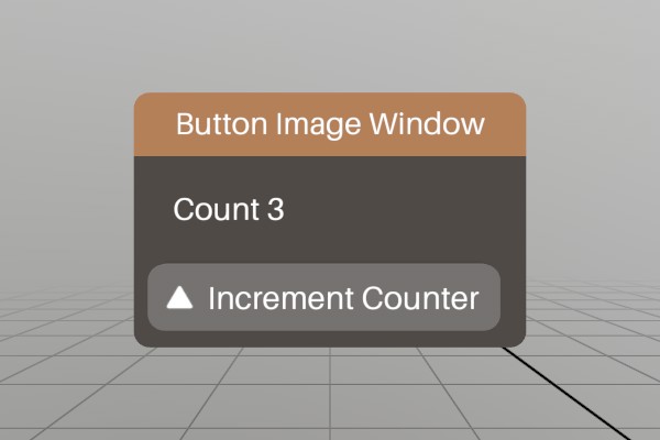
void ButtonImgWindow(ref Pose windowPose, ref int counter)
{
	UI.WindowBegin("Button Image Window", ref windowPose);

	UI.Label($"Count {counter}");
	if (UI.ButtonImg("Increment Counter", Sprite.ArrowUp))
		counter++;

	UI.WindowEnd();
}
Making a Toggle
Just to drive home the idea of how immediate mode state management
works, lets take a look at the Toggle element!

bool header = false;
void ToggleWindow(ref Pose windowPose)
{
	UI.WindowBegin("Toggle Window",
	               ref windowPose,
	               header ? UIWin.Normal : UIWin.Body);

	UI.Toggle("Show Header", ref header);

	UI.WindowEnd();
}
headeris used as a class global variable to illustrate the complete life of the variable. It could just as easily be arefparameter like thePose.
As you might expect, UI.Toggle is a UI element that will toggle a
boolean value whenever it’s pressed! Like the UI.Button, UI.Toggle
also has a return value, in this case it returns true anytime the
boolean value changes from interaction. Sometimes quite useful, but in
this case we don’t actually need an event to react to, we just use the
same boolean variable every frame when defining the window!
Though perhaps a subtle detail, this is one of the superpowers of an
immediate mode mentality. Recalculating the enum value every frame
allows us to avoid caching some separate UIWin variable in addition
to our header boolean. Our own header variable becomes a singular
source of truth that can be durable to mutation at any point in time.
Multiple sources of truth and cached values can often lead to
desynchronization bugs.
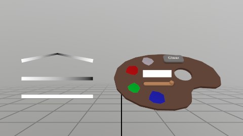
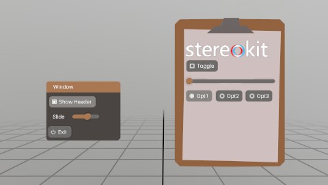
Custom Windows
StereoKit also supports the idea of objects as interfaces! Instead of putting UI elements onto windows, we can create 3D models and apply UI elements to their surface! StereoKit uses ‘handles’ to accomplish this, a grabbable area that behaves much like a window, but with a few more options for customizing layout and size.
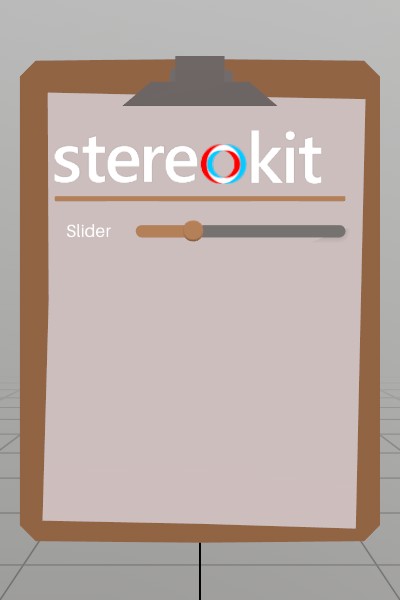
Model  clipboard  = Model .FromFile("Clipboard.glb");
Sprite logoSprite = Sprite.FromFile("StereoKitWide.png");
void CustomWindow(ref Pose windowPose, ref float slider)
{
	UI.HandleBegin("Clip", ref windowPose, clipboard.Bounds);
	// Handle also does not specify the valid layout area for the UI,
	// so we do this explicitly here. In this case, I know in advace
	// that the clipboard GLTF file has a usable surface that's about
	// 26x30cm.
	UI.LayoutArea(V.XY0(.13f, .15f), new Vec2(.26f, .3f));

	// Since the Handle does not draw anything, we must draw our own
	// visual! We can draw this at Identity because HandleBegin
	// pushes its pose onto the transform hierarchy. This is _not_ a
	// UI element, it's just a regular Model asset and does not use
	// any of the UI's layout tools.
	clipboard.Draw(Matrix.Identity);

	UI.Image(logoSprite, V.XY(.22f, 0));

	UI.HSeparator();

	UI.Label("Slider");
	UI.SameLine();
	UI.HSlider("slideId", ref slider, 0, 1);

	UI.HandleEnd();
}
As you can see, it looks basically like a Window with the Begin/End
pattern, but with the extra LayoutArea and custom visual. You can
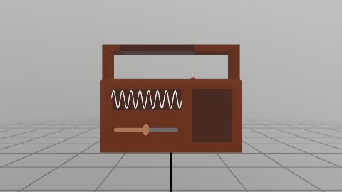
find another more complex example of using GLTFs for UI with a radio
model over in the demos.
There’s also a few new UI elements here! A UI.Image to decorate the
interface a bit, a UI.HSeparator to visually separate or group
elements, a UI.Label to put a small bit of text on the UI (see
UI.Text for longer pieces of text!), UI.SameLine to manipulate the
layout and put the next UI element on the same ‘line’, and then
UI.HSlider, a nice tool for changing float values.
You can check out the Tearsheet Demo to see the vast majority of UI elements in use, or check the UI class docs for a complete list of UI related elements.
UI Layout
So far, our UI layout has been pretty simplistic! Each UI element has
for the most part determined its own size, and then advanced to the
next layout line for the next element. All StereoKit UI functions have
a number of variants to them, typically one that auto-layouts as much
as possible, one that accepts an explicit size, and one that completely
bypasses StereoKit’s layout system. The ones that bypass SK’s layout
system are named differently, UI.ButtonAt, UI.HSliderAt, etc.,
rather than just being overloads.
UI.___Atfunctions are useful when designing custom elements, element groups, or your own layout system, but are not often used at top level.
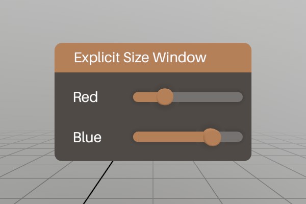
Here’s how explicitly sized UI elements work.
void ExplicitSizeWindow(ref Pose  windowPose,
                        ref float slider1,
                        ref float slider2)
{
	UI.WindowBegin("Explicit Size Window",
	               ref windowPose,
	               new Vec2(.2f, 0));

	// Explicit sizes on labels can be really useful for forcing the
	// text into visual columns, rather than ragged edges of auto
	// sized text.
	UI.Label("Red", new Vec2(.06f, 0));
	UI.SameLine();
	UI.HSlider("slideId1", ref slider1, 0, 1);

	UI.Label("Blue", new Vec2(.06f, 0));
	UI.SameLine();
	UI.HSlider("slideId2", ref slider2, 0, 1);

	UI.WindowEnd();
}
When a size of 0 is provided for either axis, StereoKit will auto-size that dimension. For a Window, it will grow in that direction. For UI elements, they will generally take all remaining space for the X axis, and use UI.LineHeight for the vertical axis.
You can also add extra space between elements, or reserve empty chunks of layout space. Reserving space is a common trick for when you need to draw something custom on the UI, but it can also be empty!
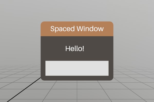
void SpaceWindow(ref Pose windowPose)
{
	UI.WindowBegin("Spaced Window", ref windowPose);

	// Add horizontal space in front of the label equal to the height
	// of one standard UI line.
	UI.HSpace(UI.LineHeight);
	UI.Label("Hello!");

	// Reserve a full UI line, and draw a cube there using non-UI
	// drawing functions.
	Bounds layout = UI.LayoutReserve(Vec2.Zero, false, 0.001f);
	Mesh.Cube.Draw(Material.Default,
	               Matrix.TS(layout.center, layout.dimensions));

	UI.WindowEnd();
}
Layout Cuts and Hierarchy
StereoKit also has a hierarchical layout area system, so you can always
push and pop Layout areas onto the Layout stack, and fill them with
elements. This can be arbitrary rectangles within the current Surface,
rectangles reserved on the current Layout via UI.LayoutReserve, or
areas “cut” from the current Layout with UI.LayoutPushCut.
See
UI.Push/PopSurfaceto create new UI Surfaces with different origins and orientations.UI.WindowBegin/Endinternally callsUI.Push/PopSurfacewith the Window’s Pose, but you can do the same at any point as well!
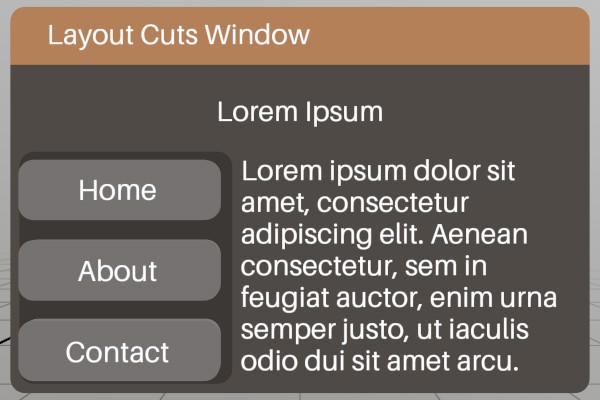
void LayoutCutsWindow(ref Pose windowPose)
{
	UI.WindowBegin("Layout Cuts Window",
	               ref windowPose,
	               new Vec2(0.3f, 0));

	UI.LayoutPushCut(UICut.Top, UI.LineHeight);
	// Center some text in this "Cut". We can do this by filling the
	// current layout by specifying a size of UI.LayoutRemaining, and
	// then setting the text to align to the center of its element
	// region.
	UI.Text("Lorem Ipsum",
	        Align  .Center,
	        TextFit.None,
	        UI     .LayoutRemaining);
	UI.LayoutPop();

	UI.LayoutPushCut(UICut.Left, 0.1f);
	// We can use a non-layout "At" panel element to add a decorative
	// background to this entire layout area, without affecting the
	// layout of the elements in it.
	UI.PanelAt(UI.LayoutAt, UI.LayoutRemaining);
	// Explicit size these buttons to ensure they all take the same
	// width, instead of sizing to fit their text.
	UI.Button("Home",    V.XY(0.1f, 0));
	UI.Button("About",   V.XY(0.1f, 0));
	UI.Button("Contact", V.XY(0.1f, 0));
	UI.LayoutPop();

	// Fill the remaining uncut area with text.
	UI.Text("Lorem ipsum dolor sit amet, consectetur adipiscing "   +
	        "elit. Aenean consectetur, sem in feugiat auctor, enim "+
	        "urna semper justo, ut iaculis odio dui sit amet arcu.");

	UI.WindowEnd();
}
An Important Note About IDs
StereoKit does store a small amount of information about the UI’s state
behind the scenes, like which elements are active and for how long.
This internal data is attached to the UI elements via a combination of
their own ids, and the parent Window/Handle’s id!
This means you should be careful to NOT re-use ids within a
Window/Handle, otherwise you may find ghost interactions with
elements that share the same ids. If you need to have elements with the
same id, or if perhaps you don’t know in advance that all your
elements will certainly be unique, UI.PushId and UI.PopId can be
used to mitigate the issue by using the same hierarchy id mixing that
the Windows use to prevent collisions with the same ids in other
Windows/Handles.
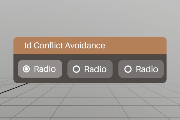
Here’s a set of Radio options, but all of them have the same name/id!
Pushing a unique id onto the id stack prevents the Radio ids from
conflicting!
void IdWindow(ref Pose windowPose, ref int option)
{
	UI.WindowBegin("Id Conflict Avoidance", ref windowPose);

	UI.PushId(1);
	if (UI.Radio("Radio", option == 1)) option = 1;
	UI.PopId();

	UI.SameLine();
	UI.PushId(2);
	if (UI.Radio("Radio", option == 2)) option = 2;
	UI.PopId();

	UI.SameLine();
	UI.PushId(3);
	if (UI.Radio("Radio", option == 3)) option = 3;
	UI.PopId();

	UI.WindowEnd();
}
What’s Next?
And there you go! That’s how UI works in StereoKit, pretty reasonable, huh? For further reference, and more UI methods, checkout the UI class documentation.
If you’d like to see the complete code for this sample, check it out on Github!
Using Hands
Using Hands
StereoKit uses a hands first approach to user input! Even when hand-sensors aren’t available, hand data is simulated instead using existing devices! For example, Windows Mixed Reality controllers will blend between pre-recorded hand poses based on button presses, as will mice. This way, fully articulated hand data is always present for you to work with!
Accessing Joints
Since hands are so central to interaction, accessing hand information needs to be really easy to get! So here’s how you might find the fingertip of the right hand! If you ignore IsTracked, this’ll give you the last known position for that finger joint.
Hand hand = Input.Hand(Handed.Right);
if (hand.IsTracked)
{
	Vec3 fingertip = hand[FingerId.Index, JointId.Tip].position;
}
Pretty straightforward! And if you prefer calling a function instead of using the
[] operator, that’s cool too! You can call hand.Get(FingerId.Index, JointId.Tip)
instead!
If that’s too granular for you, there’s easy ways to check for pinching and gripping! Pinched will tell you if a pinch is currently happening, JustPinched will tell you if it just started being pinched this frame, and JustUnpinched will tell you if the pinch just stopped this frame!
if (hand.IsPinched) { }
if (hand.IsJustPinched) { }
if (hand.IsJustUnpinched) { }

if (hand.IsGripped) { }
if (hand.IsJustGripped) { }
if (hand.IsJustUngripped) { }
These are all convenience functions wrapping the hand.pinchState bit-flag, so you
can also use that directly if you want to do some bit-flag wizardry!
Hand Menu
Lets imagine you want to make a hand menu, you might need to know if the user is looking at the palm of their hand! Here’s a quick example of using the palm’s pose and the dot product to determine this.
static bool HandFacingHead(Handed handed)
{
	Hand hand = Input.Hand(handed);
	if (!hand.IsTracked)
		return false;

	Vec3 palmDirection   = (hand.palm.Forward).Normalized;
	Vec3 directionToHead = (Input.Head.position - hand.palm.position).Normalized;

	return Vec3.Dot(palmDirection, directionToHead) > 0.5f;
}
Once you have that information, it’s simply a matter of placing a window off to the side of the hand! The palm pose Right direction points to different sides of each hand, so a different X offset is required for each hand.
public static void DrawHandMenu(Handed handed)
{
	if (!HandFacingHead(handed))
		return;

	// Decide the size and offset of the menu
	Vec2  size   = new Vec2(4, 16);
	float offset = handed == Handed.Left ? -2-size.x : 2+size.x;

	// Position the menu relative to the side of the hand
	Hand hand   = Input.Hand(handed);
	Vec3 at     = hand[FingerId.Little, JointId.KnuckleMajor].position;
	Vec3 down   = hand[FingerId.Little, JointId.Root        ].position;
	Vec3 across = hand[FingerId.Index,  JointId.KnuckleMajor].position;

	Pose menuPose = new Pose(
		at,
		Quat.LookAt(at, across, at-down) * Quat.FromAngles(0, handed == Handed.Left ? 90 : -90, 0));
	menuPose.position += menuPose.Right * offset * U.cm;
	menuPose.position += menuPose.Up * (size.y/2) * U.cm;

	// And make a menu!
	UI.WindowBegin("HandMenu", ref menuPose, size * U.cm, UIWin.Empty);
	UI.Button("Test");
	UI.Button("That");
	UI.Button("Hand");
	UI.WindowEnd();
}
Interactors
StereoKit’s interactions are driven by Interactors - capsules of
input that can come from hands, controllers, the mouse, and more!
You can enumerate every Interactor with Interactor.All and filter
them using Interactor.Source, which makes it a great way to find
input rays like the hand’s aim ray here.
public static void DrawInteractors()
{
	foreach (Interactor actor in Interactor.All)
	{
		// We only want the hand aim rays here: Line shaped interactors
		// that come from a hand source.
		bool isHand = (actor.Source & (InteractorSource.HandLeft | InteractorSource.HandRight)) != 0;
		if (!isHand || actor.Type != InteractorType.Line || !actor.Tracked.IsActive())
			continue;

		Vec3 dir = (actor.End - actor.Start).Normalized;
		Lines.Add    (actor.Start, actor.Start + dir * 0.5f, Color.White, Units.mm2m);
		Lines.AddAxis(actor.Motion);
	}
}
The code in context for this document can be found on Github here!
Using The Simulator
Using the Simulator
As a developer, you can’t realistically spend all of your development in a headset just yet. So, a decent grasp over StereoKit’s fallback flatscreen MR simulator is particularly helpful! This is basically a 2D window that allows you to move around and interact, without requiring an OpenXR runtime or headset.
Simulator Controls
When you start the simulator, you’ll find that your mouse controls the right hand by default. This is a complete simulation of an articulated hand, so you’ll have access to all the joints the same way you would a real tracked hand. The hand becomes tracked when the mouse enters the window, and untracked when leaving the window. The pointer ray, which is normally a shoulder->hand ray, will be along the mouse ray instead.
Mouse Controls:
- Left Mouse - Hand animates to a Pinch gesture.
- Right Mouse - Hand animates to a Grip gesture.
- Left + Right - Hand animates to a closed fist.
- Scroll Wheel - Moves the hand toward or away from the user.
- Shift + Right - Mouse-look / rotate the head.
- Left Alt - Eye tracking will point along the ray indicated by the mouse.
- Ctrl + Shift - Switch between controlling left hand, right hand, or no hand.
To move around in space, you’ll find controls that should be familiar to those that play first-person games! Hold Left Shift to enable this.
Keyboard Controls:
- Shift+W - Move forward.
- Shift+A - Move left.
- Shift+S - Move backwards.
- Shift+D - Move right.
- Shift+Q - Move down.
- Shift+E - Move up.
Simulator API
There’s a few bits of functionality that let you set up the simulator, or some features that may assist you in debugging or testing! Here’s a couple you may want to know about:
Simulator Enable/Disable
By default, StereoKit will fall back to the flatscreen simulator if OpenXR fails to initialize for any reason (like, headset not plugged in, or OpenXR not present). You can modify this behavior at initialization time when defining your SKSettings for SK.Init.
SKSettings settings = new SKSettings {
	appName                = "Flatscreen Simulator",
	assetsFolder           = "Assets",
	// This tells StereoKit to always start in a 2D simulator
	// window, instead of an immersive MR environment.
	mode                   = AppMode.Simulator,
	// Setting this to true will prevent StereoKit from creating the
	// fallback simulator when OpenXR fails to initialize. This is
	// important when shipping a final application to users.
	noFlatscreenFallback   = true,
};
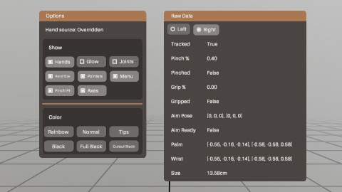
Overriding Hands
A number of functions are present that can make unit test and complex input simulation possible. For a full example of this, the DebugToolWindow in the Test project has a number of sample utilities for recording and playing back input.
Overriding the hands is one important element that you may want
to do! Input.HandOverride
will set the hand input to a very specific pose, and hold that
pose until you call Input.HandOverride again with a new pose,
or call Input.HandClearOverride
to restore control back to the user.
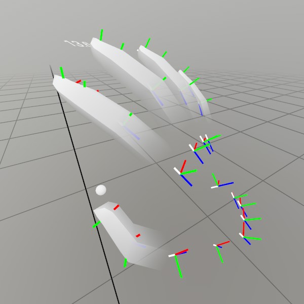
 This screenshot is generated fresh every StereoKit release using Input.HandOverride, to ensure consistency!
// These 25 joints were printed using code from a session with a real
// hand.
HandJoint[] joints = new HandJoint[] { new HandJoint(new Vec3(0.132f, -0.221f, -0.168f), new Quat(-0.445f, -0.392f, 0.653f, -0.472f), 0.021f), new HandJoint(new Vec3(0.132f, -0.221f, -0.168f), new Quat(-0.445f, -0.392f, 0.653f, -0.472f), 0.021f), new HandJoint(new Vec3(0.141f, -0.181f, -0.181f), new Quat(-0.342f, -0.449f, 0.618f, -0.548f), 0.014f), new HandJoint(new Vec3(0.139f, -0.151f, -0.193f), new Quat(-0.409f, -0.437f, 0.626f, -0.499f), 0.010f), new HandJoint(new Vec3(0.141f, -0.133f, -0.198f), new Quat(-0.409f, -0.437f, 0.626f, -0.499f), 0.010f), new HandJoint(new Vec3(0.124f, -0.229f, -0.172f), new Quat(0.135f, -0.428f, 0.885f, -0.125f), 0.024f), new HandJoint(new Vec3(0.103f, -0.184f, -0.209f), new Quat(0.176f, -0.530f, 0.774f, -0.299f), 0.013f), new HandJoint(new Vec3(0.078f, -0.153f, -0.225f), new Quat(0.173f, -0.645f, 0.658f, -0.349f), 0.010f), new HandJoint(new Vec3(0.061f, -0.135f, -0.228f), new Quat(-0.277f, 0.674f, -0.623f, 0.283f), 0.010f), new HandJoint(new Vec3(0.050f, -0.125f, -0.227f), new Quat(-0.277f, 0.674f, -0.623f, 0.283f), 0.010f), new HandJoint(new Vec3(0.119f, -0.235f, -0.172f), new Quat(0.147f, -0.399f, 0.847f, -0.318f), 0.024f), new HandJoint(new Vec3(0.088f, -0.200f, -0.211f), new Quat(0.282f, -0.603f, 0.697f, -0.268f), 0.012f), new HandJoint(new Vec3(0.056f, -0.169f, -0.216f), new Quat(-0.370f, 0.871f, -0.308f, 0.099f), 0.010f), new HandJoint(new Vec3(0.045f, -0.156f, -0.195f), new Quat(-0.463f, 0.884f, -0.022f, -0.066f), 0.010f), new HandJoint(new Vec3(0.047f, -0.155f, -0.178f), new Quat(-0.463f, 0.884f, -0.022f, -0.066f), 0.010f), new HandJoint(new Vec3(0.111f, -0.244f, -0.173f), new Quat(0.182f, -0.436f, 0.778f, -0.414f), 0.022f), new HandJoint(new Vec3(0.074f, -0.213f, -0.205f), new Quat(-0.353f, 0.622f, -0.656f, 0.244f), 0.011f), new HandJoint(new Vec3(0.046f, -0.189f, -0.204f), new Quat(-0.436f, 0.891f, -0.073f, -0.108f), 0.010f), new HandJoint(new Vec3(0.048f, -0.184f, -0.182f), new Quat(-0.451f, 0.811f, 0.264f, -0.263f), 0.010f), new HandJoint(new Vec3(0.061f, -0.188f, -0.168f), new Quat(-0.451f, 0.811f, 0.264f, -0.263f), 0.010f), new HandJoint(new Vec3(0.105f, -0.250f, -0.170f), new Quat(0.219f, -0.470f, 0.678f, -0.521f), 0.020f), new HandJoint(new Vec3(0.062f, -0.228f, -0.196f), new Quat(-0.444f, 0.610f, -0.623f, 0.206f), 0.010f), new HandJoint(new Vec3(0.044f, -0.215f, -0.192f), new Quat(-0.501f, 0.841f, -0.094f, -0.183f), 0.010f), new HandJoint(new Vec3(0.048f, -0.209f, -0.176f), new Quat(-0.521f, 0.682f, 0.251f, -0.448f), 0.010f), new HandJoint(new Vec3(0.061f, -0.207f, -0.168f), new Quat(-0.521f, 0.682f, 0.251f, -0.448f), 0.010f), new HandJoint(new Vec3(0.098f, -0.222f, -0.191f), new Quat(0.308f, -0.906f, 0.288f, -0.042f), 0.000f), new HandJoint(new Vec3(0.131f, -0.251f, -0.164f), new Quat(0.188f, -0.436f, 0.844f, -0.248f), 0.000f) };

Input.HandOverride(Handed.Right, joints);
Drawing
Drawing content with StereoKit
Generally, the first thing you want to do is get content on-screen! Or in-visor? However it’s said, in this guide we’re going to explore the various ways to display some holograms!
At its core, drawing things in 3D is done through a combination of
Meshes and
Materials. A Mesh
is a collection of triangles in 3D space that describe where the
surface of that 3D object is. And a Material is then a collection
of parameters, Textures
(2d images), and Shader code that are combined to describe the
visual properties of the Mesh’s surface!
 Meshes are made from triangles!
And in addition to that, you’ll need to know a little bit about
matrices, which are a math construct used to describe the location,
orientation and scale of geometry within the 3D space! A Matrix
isn’t difficult the way we’re using it, so don’t worry if math
isn’t your thing.
And then StereoKit also has a Model,
which is a high level combination of Meshes, Material, Matrices,
and a few more things! Most of the time, you’ll probably be drawing
Models loaded from file, but it’s important to have options.
Then lastly, StereoKit has easy systems for drawing Lines,
Text, Sprites
and various other things! These are still based on Meshes and
Materials under the hood, but have some complex features that can
make them difficult to build from scratch.
Meshes and Materials
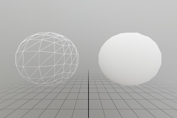
To simplify things here, we’re going to use the built-in assets,
Mesh.Sphere
and Material.Default.
Mesh.Sphere is a built-in mesh generated using math when StereoKit
starts up, and Material.Default is a high performance simple
Material that serves as StereoKit’s default Material. (For more
built-in assets, see the Defaults)
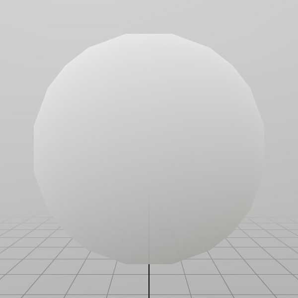
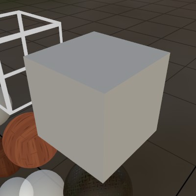
Mesh.Sphere.Draw(Material.Default, Matrix.Identity);
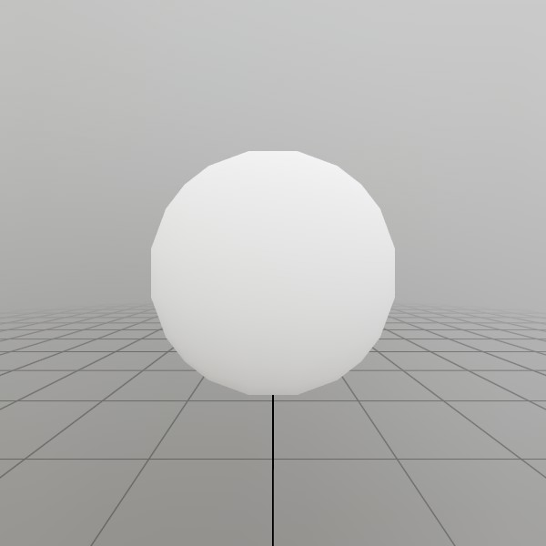 Drawing the default sphere Mesh with the default Material.
Matrix.Identity
can be though of as a ‘No transform’ Matrix, so this is drawing the
sphere at the origin of the 3D space.
That’s pretty straightforward! StereoKit will get this Mesh/Material pair onto the screen this frame. Remember that StereoKit is generally an immediate mode API, so this won’t show up for more than the current frame. If you want it to draw every frame, you’ll have to call Draw every frame!
So how do you get a Mesh to begin with? In most cases you’ll just be working with Models, but you can get a Mesh directly from a few places:
Mesh.Sphere,Mesh.Cube, andMesh.Quadare built-in mesh assets that are handy to have around.Meshhas a number of static methods for generating procedural shapes, such asMesh.GenerateRoundedCubeorMesh.GeneratePlane.- A Mesh can be extracted from one of a Model’s nodes.
- You can create a Mesh from a list of vertices and indices. This is more advanced, but check the sample here.
And where do you get a Material? Well,
- See built-in Materials like
Material.PBRfor high-quality surface orMaterial.Unlitfor fast/stylistic surfaces. - A Material constructor can be called with a Shader. Check out the Material guide for in-depth usage (Materials and Shaders are a lot of fun!).
- You can call
Material.Copyto create a duplicate of an existing Material.
Matrix basics
If you like math, this explanation is not really for you! But if
you like results, this will get you going where you need to go. The
important thing to know about a Matrix,
is that it’s a good way to represent an object’s transform (Translation,
Rotation, and Scale).
StereoKit provides a number of Matrix creation methods that allow you to easily create Translation/Rotation/Scale matrices.
// The identity matrix is the matrix equivalent of '1'. You can also
// think of it as a 'no-transform' matrix.
Matrix transform = Matrix.Identity;

// Translates points 1 meter up the Y axis
transform = Matrix.T(0, 1, 0);

// Scales a point by (2,2,2), rotates it 180 on the X axis, and
// then translates it up 1 meter up the Y axis.
transform = Matrix.TRS(
	new Vec3(0,1,0),
	Quat.FromAngles(180, 0, 0),
	new Vec3(2,2,2));

// To draw a cube at (0,-10,0) that's rotated 45 degrees around its Y
// axis:
Mesh.Cube.Draw(Material.Default, Matrix.TR(0,-10,0, Quat.FromAngles(0,45,0)));
The TRS methods have a lot of permutations that can help make your matrix creation code a bit shorter. Like, if you don’t need to add scale to your TRS matrix, there’s the TR variant! No rotation? Try TS! Etc. etc.
Now. Even more interesting, is that many Matrices can be combined
into a single Matrix representing multiple transforms! This is done
via multiplication, and an important note here is that matrix
multiplication is not commutative, that is: A*B != B*A, so the
order in which you combine your matrices is important.
This can let you do things like, rotate around a pivot point, or build a hierarchy of transforms! A parent/child position hierarchy can be described pretty easily this way:
Matrix parentTransform = Matrix.TR(10, 0, 0, Quat.FromAngles(0, 45, 0));
Matrix childTransform  = Matrix.TS( 1, 1, 0, 0.2f);

Mesh.Cube.Draw(Material.Default, parentTransform);
Mesh.Cube.Draw(Material.Default, childTransform * parentTransform);
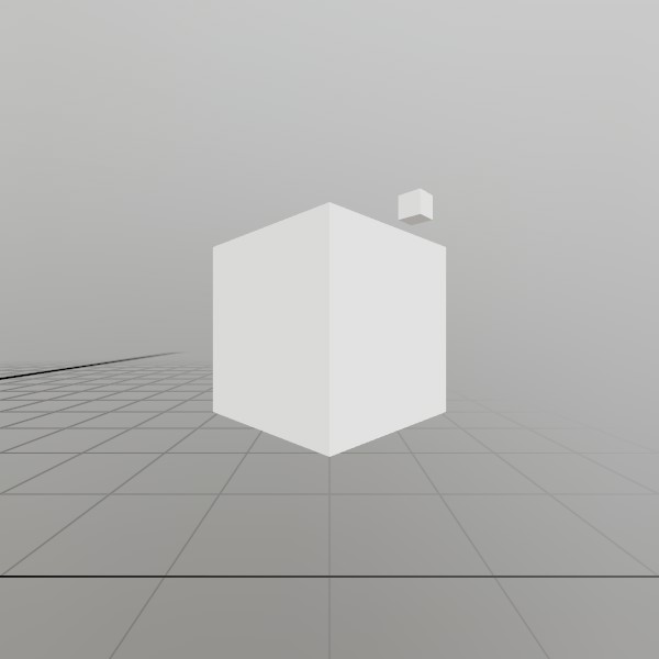 The smaller
 childTransform is relative to parentTransform via multiplication.
Models
The easiest way to draw complex content is through a Model! A Model is basically a small scene of Mesh/Material pairs at positions with hierarchical relationships to each other. If you’re creating art in a 3D modeling tool such as Blender, then this is basically a full representation of the scene you’ve created there.
Just put your 3D model in the project’s Assets folder, then load it like this once during initialization!
Model model = Model.FromFile("DamagedHelmet.gltf");
And since a model already has all its information within it, all you need to do is provide it with a location!
model.Draw(Matrix.T(10, 10, 0));
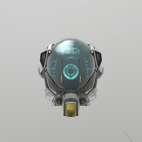 StereoKit’s main format is the .gltf file.
So… that was also pretty simple! The only real trick with Models is getting one in the first place, but even that’s not too hard. There’s a lot you can do with a Model beyond just drawing it, so for more details on that, check out the 3D Asset guide!
But here’s the quick list of where you can get a Model to begin with:
Model.FromFileis the easiest, most common way to get a Model!Model.FromMeshwill let you create a very simple Model with a single function call.- The Model constructor lets you create an empty Model, which you can then fill with ModelNodes via
Model.AddNode - You can call
Model.Copyto create a duplicate of an existing Model.
Lines
Being able to easily draw a line is incredibly useful for
debugging, and generally quite practical for many other purposes as
well! StereoKit has the Lines
class to assist with this, and is pretty straightforward to use.
There’s a few variations, but at it’s simplest, it’s a few points,
a color, and a thickness.
Lines.Add(
	new Vec3(2, 2, 0),
	new Vec3(3, 2.5f, 0),
	Color.Black, 1*U.cm);
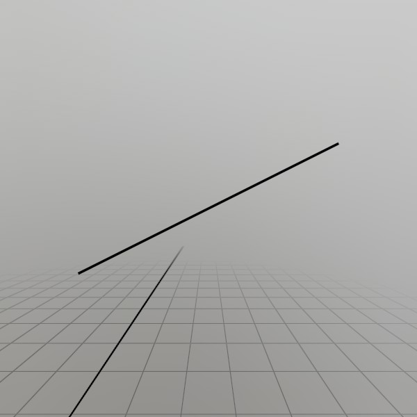 You can also draw Rays, Poses, and multicolored lists of lines!
Text
Text is drawn with a collection of rectangular quads, each mapped to a character glyph on a texture. StereoKit supports rendering any Unicode glyphs you throw at it, as long as the active Font has that glyph defined in it! This means you can work with all sorts of different languages right away, without any baking or preparation.
To draw text with the default Font, you can do this!
Text.Add("こんにちは", Matrix.T(-10, 10,0));
 ‘Hello’ in Japanese, I’m pretty sure.
You can create additional font styles and fonts to use with text
drawing, and there are a number of overloads for Text.Add
that allow you to change the layout or constrain to a particular
area. Check the docs for the method for more information about that!
Sprites
Drawing an image can be done in a few ways, the simplest being with
the Sprite class!
Much like a Model, you can load a Sprite at initialization from
a file! StereoKit supports most common image formats, and if you’re
looking to eke out some extra performance in your app, KTX2 images
include some extra features that can reduce load times and GPU
memory usage.
Sprite sprite = Sprite.FromFile("StereoKitWide.png");
Drawing is then the same as with a Model, but with some extra
options for placement, and automatic handling of the image’s aspect
ratio. Here we’re placing the center of the image at (0, 10, 0),
but we could just as easily place the top left of the image at
that position instead! The scale here is also equivalent to the
size of the image’s vertical axis, so this Sprite will be 0.5
meters tall.
sprite.Draw(Matrix.TS(0, 10, 0, 0.5f), Pivot.Center);
![]()
If you already have a Tex with your image loaded, you can pretty
easily create a Sprite from it. One catch is that most of the
time with Sprites, you want the image to Clamp at the edges,
otherwise you may encounter a bit of bleed when the default Wrap
behavior wraps around the edges.
// Creating a sprite from a Tex
Tex logo = Tex.FromFile("StereoKitWide.png");
tex.AddressMode = TexAddress.Clamp;

Sprite sprite = Sprite.FromTex(logo);
If you want to draw your image with a custom Shader or Material
options, you’ll want to bypass the Sprite class and draw the
Tex manually! For this, we’ll want to set up our Material in a
way that mimics the Sprite’s behavior. Notably, it should support
transparency, and not cull backfaces to make it visible from
behind.
// In initialization, create a Material like this:

Tex logo = Tex.FromFile("StereoKitWide.png");
tex.AddressMode = TexAddress.Clamp;

Material spriteMaterial = Material.Unlit.Copy();
spriteMaterial.Transparency = Transparency.Blend;
spriteMaterial.FaceCull     = Cull.None;
spriteMaterial[MatParamName.DiffuseTex] = logo;
And then Draw it on a Mesh.Quad, manually accounting for the
image’s aspect ratio!
float aspect = logo.Width / (float)logo.Height;
Vec3  scale  = V.XYZ(aspect,1,1) * 0.5f;
Mesh.Quad.Draw(spriteMaterial, Matrix.TS(-30, 10, 0, scale));
Cool!
So that’s the highlights! There’s plenty more to draw and more tricks to be learned, but this is a great start! There’s treasures in the documentation, so hunt around in there for more samples. You may also be interested in the Materials guide for advanced rendering code, or the Model guide (coming soon), for managing your visible content!
If you’d like to see all the code for this document, check it out here!
Working with 3D Assets
Working with 3D Assets
StereoKit’s core 3D asset format is the GLTF! While there is still support for other formats, like STL, OBJ and PLY, GLTF is StereoKit’s preferred format of choice. It has a well defined modern specification, and a large collection of quality tooling available in the ecosystem.
GLB is still just the “binary” format of GLTF, typically with all related textures bundled inside it.
I’ve found Blender to have a very nice GLTF exporter! So if your tool of choice doesn’t support GLTF yet, exporting to Blender for a final pass can be a good approach! However, most tools will at least have a plugin for GLTF export.
Most 3D asset creation tools have material systems more geared towards cinematic rendering, rather than realtime rendering, so it can be important to understand how materials are exported in GLTF format (via Blender), as well as how StereoKit interprets them.
Materials
StereoKit’s rules for interpreting GLTF materials are mostly straightforward!
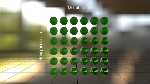
If the GLTF material is PBR (the normal case), StereoKit will use a PBR shader. It uses the metallic roughness definition of PBR, and does not currently support the specular/glossiness GLTF extension.
If the GLTF material is Unlit (In Blender, this is a material using a Background or Emission surface) StereoKit will use an Unlit shader.
If the GLTF material has alpha mask on, StereoKit will use a “clip” variant of the PBR or Unlit shaders that discards transparent pixels.
It’s good to note that GLTF supports vertex color data, and almost all StereoKit default shaders support vertex coloring! Vertex colors don’t often show in 3D asset tools out-of-the-box, but this can be a nice way to add cheap baked lighting to Unlit materials, or add color variation to looping textures, or other creative uses!
Lightmaps
StereoKit also supports a Ligtmapped material from GLTF files! This is a somewhat non-standard setup not found in the original spec, but is a very useful one for performant applications. It is not unusual to find bad GLTFs where lighting data is baked down into the diffuse texture, expanding a “looped” texture into something much much larger. This consumes much more RAM than preserving the original looped texture and combining it with a separate lightmap texture!
Instead, if StereoKit encounters a material that has:
- An emissive texture (the base color, like an Unlit material)
- An occlusion texture using the second UV channel (the lightmap)
- No texture for PBR base color
- No texture for PBR metal/roughness
This will trigger StereoKit to switch to a high-performance Unlit + Lightmap shader.
Best Practices
Optimize with GLTFPack
StereoKit supports all the GLTF extensions required for GLTFPack to work properly! Mesh compression, KTX textures, quantization and transform all work. If you can optimize your GLTF files in advance with a tool like this, you can get 50-80% smaller files (even on GPU!), much faster load times, and improved render performance!
gltfpack.exe -cc -tc -i modelName.glb -o modelName.opt.glb
This is effective with just about any model, but especially for photogrammetry-like assets this type of optimization is absolutely critical!
Backface Culling
GLTF supports a setting for enabling or disabling backface culling, an important optimization that will skip rendering triangles that face away from the viewer. Having backface culling ON can improve performance significantly, and in most normal cases, is completely unnoticeable! For whatever reason, many 3D tools seem to disable backface culling by default, and this mistake is very common to find in many GLTF files!
Always make sure your materials have backface culling ON whenever possible!

PBR Shaders vs. Unlit
Physically Based shaders look great! But the accuracy they provide costs a lot of computation. If you can use an Unlit material instead, do it!
For more information about shaders and material, check out StereoKit’s Material guide!
References
A quick note about how Asset types (Model/Material/Tex, etc.) work in StereoKit!
When you work with an Asset, you’ll want to keep in mind that you’re actually working with a reference to the Asset! Sometimes the handle you have is just one of many references to the Asset, and so changing the Asset will affect all other references to it as well.
If you want to change an Asset’s property without affecting other
references to that Asset, then you should Copy() that Asset, and modify
that new, unique instance instead! This is why you’ll frequently see the
example code doing something like Material.Default.Copy() before
changing any of the properties.
GLTF extension support
On a more technical note, here’s a specific list of what GLTF extensions StereoKit supports.
- KHR_materials_unlit
- KHR_mesh_quantization
- KHR_texture_basisu
- KHR_texture_transform (not rotation)
- EXT_meshopt_compression
Notes About Alternative Formats
Why no FBX you might ask? FBX is an old and poorly defined format. Early versions of StereoKit supported it, but it ended up being far too much pain. Among other things, FBX has no reliable concept of “units” or even “which direction is forward”.
Why not USD? USD unfortunately has no format specification! It’s less of a file format, and more of a library. As such, it has a very poor tooling ecosystem making the “format” difficult to support well. If you want to support USD correctly, you must use the singular implementation of USD. And unfortunately, that implementation doesn’t pass my smell test for code quality.
Working with Materials
Working with Materials
Materials describe the visual appearance of everything on-screen, so having a solid understanding of how they work is important to making a good looking application! Fortunately, StereoKit comes with some great tools built-in, and Materials can be a lot of fun to work with!
Using Materials
We’ve already seen that we can use a Material like this:
Mesh.Sphere.Draw(Material.Default, Matrix.Identity);
This uses the primary default Material, which is a simple but extremely fast and flexible Material. The default is great, but not very interesting, it’s just a white matte surface! If we want it to look different, we’ll have to change some of the Material’s parameters.
Before we can change the Material’s parameters, I’d like to point out an important fact! StereoKit does not draw objects immediately when Draw is called: instead, it stores draw information, and at the end of the frame it will sort, cull, and batch everything, and then draw it all at once! Since a Material is a shared Asset, Meshes are drawn with the Material as it appears at the end of the frame!
This means you cannot take one Material, modify it, draw, modify it again, draw, and expect them to look different. Both draw calls share the same Material Asset, and will look the same. Instead, you must make a new Material for each visually distinct surface. Here’s what that looks like:
Material from Copy
Material newMaterial;
void InitNewMaterial()
{
// Start by just making a duplicate of the default! This creates a new
// Material that we're free to change as much as we like.
newMaterial = Material.Default.Copy();
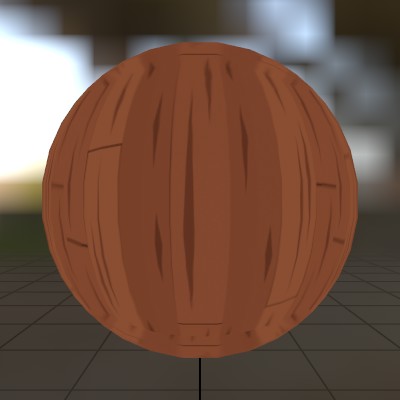
// Assign an image file as the primary color of the surface.
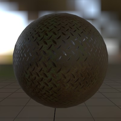
newMaterial[MatParamName.DiffuseTex] = Tex.FromFile("floor.png");
// Tint the whole thing greenish.
newMaterial[MatParamName.ColorTint] = Color.HSV(0.3f, 0.4f, 1.0f);
}
void StepNewMaterial()
{
Mesh.Sphere.Draw(newMaterial, Matrix.T(0,-3,0));
}
 It’s uh… not the most glamorous material!
Not all Materials will have the same parameters, and in fact, parameters can vary wildly from Material to Material! This comes from the Shader code that each Material has embedded at its core. The Shader runs on the GPU, describes how each vertex is projected onto the screen, and calculates the color of every pixel. Since each shader program is different, each one has different parameters it works with!
While MatParamName
helps to codify and standardize common parameter names, it’s always
best to be somewhat familiar with the Shader that the Material is
using.
For example, Material.Default uses this Shader, and you can see the parameters listed at the top:
//--color:color = 1,1,1,1
//--tex_scale   = 1
//--diffuse     = white

float4    color;
float     tex_scale;
Texture2D diffuse : register(t0);
Shaders use data embedded in comments to assign default values to
material properties, the //-- indicates this. So in this case,
color is a float4 (Vec4 or Color in C#), with a default value of
1,1,1,1, white. This maps to MatParamName.ColorTint,
but you could also use the name directly:
newMaterial["color"] = Color.HSV(0.3f, 0.2f, 1.0f);.
Materials also have a few properties that aren’t part of the Shader, things like depth testing/writing, transparency, face culling, or wireframe.
Material from Shader
You can also create a completely new Material directly from a Shader!
StereoKit does keep the default Shaders around in the Shader
class for this purpose, but you can also use Shader.FromFile to load a
pre-compiled shader file, and use that instead. More on that in the
Shader guide (coming soon).
Material shaderMaterial;

void InitShaderMaterial()
{
	// Instead of copying Material.Default, we're creating a completely new
	// Material directly from a Shader.
	shaderMaterial = new Material(Shader.Default);

	// Make it just slightly transparent
	shaderMaterial.Transparency = Transparency.Blend;
	shaderMaterial[MatParamName.ColorTint] = new Color(1, 1, 1, 0.9f);
}
void StepShaderMaterial()
{
	Mesh.Sphere.Draw(shaderMaterial, Matrix.T(0,2,0));
}
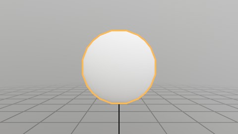
 It’s a spooky circle now.
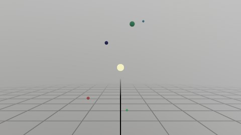
Environment and Lighting
StereoKit’s default lighting system is entirely based on environment lighting! This can drastically affect how a material looks, so choosing the right lighting can make a big difference in how your content looks. Here’s a simple white sphere again, but with a more complex lighting than the default white room.
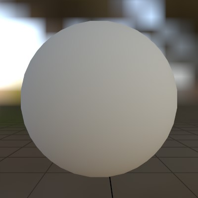
You can change the environment lighting with a nice cubemap, check out the
Renderer.SkyLight
property for a nice example of how to do this!
Materials and Performance
Since Materials are responsible for drawing everything on the screen, they have a big impact on GPU side performance! If you check your device’s performance monitor and see the GPU maxed out at 100% all the time, it’s a good moment to take a peek at how you’re working with Materials.
The first rule is that fewer Materials means better GPU utilization. GPUs don’t like switching between Shaders or even Material parameters, so if you can re-use a Material safely, you should! StereoKit does a great job of batching draw calls together to reduce this switching, but this is only effective at boosting performance if Materials are getting re-used.
The next rule is that simpler Shaders are faster. Material.Unlit is just about the fastest Material you can have, followed closely by Material.Default! Material.PBR looks great, but does a lot of work to look good. It’s very fast compared to many other PBR shaders, and quite suitable even on mobile VR headsets, but if you don’t need it, use something faster!
And lastly, small textures are faster than large ones. Textures get sampled a lot during rendering, which means moving around lots of texture memory! Remember that halving a texture’s size can reduce memory by a factor of 4!
It often helps to just see how long a draw call takes! For this, I like to use RenderDoc’s timing feature. RenderDoc works quite nicely with StereoKit’s flatscreen mode, and while this isn’t a perfect representation of performance on mobile devices, it’s a solid reference point.
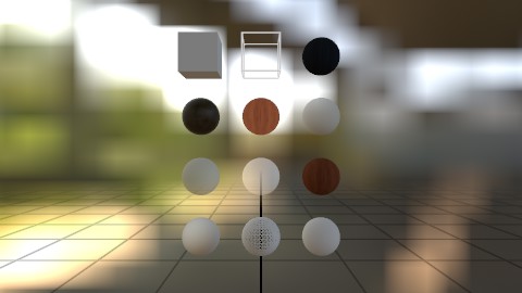
A Look at the Defaults
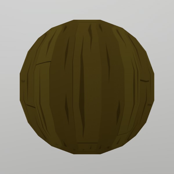
StereoKit strives to cover the basics for you, and Materials are no exception! You’ll find a collection of Materials and Shaders that are designed to be performant and good looking on mobile XR headsets, and should cover the majority of use-cases. Here’s a sampling, and check the docs for each one to see what properties they support!
Material.Default
Material.Unlit
Material.PBR
Material.UI
Material.UIBox

Debugging your App
Debugging your App
Set up for debugging
Since StereoKit’s core is composed of native code, there are a few extra steps you can take to get better stack traces and debug information! The first is to make sure Visual Studio is set up to debug with native code. This varies across .Net versions, but generally the option can be found at Project->Properties->Debug->(Native code debugging).
You may also wish to disable “Just My Code” if you’re trying to actually inspect how StereoKit’s code is behaving. This can be found under Tools->Options->Debugging->General->Enable Just My Code, and uncheck it to make sure it’s disabled.
StereoKit is set up with Source Link as of v0.3.5, which allows you to inspect StereoKit’s code directly from the relevant commit of the main repository on GitHub. Note that distributed binaries are in release format, and may not ‘step through’ as nicely as a normal debug binary would.
Check the Logs!
StereoKit outputs a lot of useful information in the logs, and there’s a chance your issue may be logged there! When submitting an issue on the GitHub repository, including a copy of your logs can really help maintainers to understand what is or isn’t happening.
All platforms will output the log through the standard debug output window,
but you can also tap into the debug logs via
Log.Subscribe. Check
the docs there for an easy Mixed Reality log window you can add to your
project.
MSBuild options
StereoKit has a collection of MSBuild variables that are designed to be
tweakable for a more configurable build experience! If you’re having issues
with the defaults, you can display the variable list during build by
turning on SKShowDebugVars in your .csproj.
<PropertyGroup>
	<SKShowDebugVars>true</SKShowDebugVars>
</PropertyGroup>
You can also consume the StereoKit SDK directly from source to allow for more invasive debugging, or even core StereoKit development! Instead of consuming the NuGet package, you can clone the StereoKit repository and point your project to it. Note that setup may be required to build from source.
<ItemGroup>
	<!-- <PackageReference Include="StereoKit" Version="0.3.10" /> -->
</ItemGroup>
<Import Project="$(ProjectDir)..\StereoKit\StereoKit\BuildStereoKitSDK.targets" />
Ask for Help
We love to hear what problems you’re running into! StereoKit is completely open source and has no analytics or surveillance tools embedded in it at all. If you have an issue, we won’t know about it unless you tell us, or we spot it ourselves!
The best place to ask for help will always be the GitHub Issues, or GitHub Discussions pages. Be sure to provide logs, platform information, and as many other details as may be relevant!
Common Issues
Here’s a short list of some common issues we’ve seen people ask about!
XR_ERROR_FORM_FACTOR_UNAVAILABLE in the logs
This is a common and expected message that basically means that OpenXR can’t find any headset attached to the system. Your headset is most likely unplugged, but may also indicate some other issue with your OpenXR runtime setup.
By default, StereoKit will fall back to the flatscreen simulator when this
error message is encountered. This behavior can be configured in your
SKSettings.
StereoKit isn’t loading my asset!
This may manifest as Null Reference Exceptions surrounding your Model/Tex/asset. The first thing to do is check the StereoKit logs, and look for messages with your asset’s filename. There will likely be some message with a decent hint available.
If StereoKit cannot find your file, make sure the path is correct, and verify your asset is correctly being copied into Visual Studio’s output folder. The default templates will automatically copy content in the project’s Assets folder into the final output folder. If your asset is not in the Assets folder, or if you have assembled your own project without using the templates, then you may need to do additional work to ensure the copy happens.
Sample Code
StereoKit Sample Code
Here are a list of small demos that illustrate how certain parts of StereoKit works!
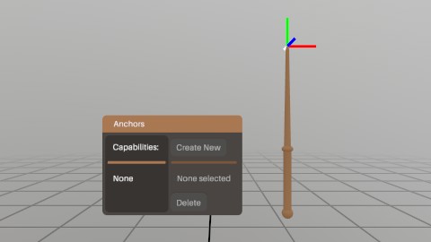
Anchors
This demo uses StereoKit’s Anchor API to add, remove, and load spatial anchors that are locked to local physical locations. These can be used for persisting locations across sessions, or increasing the stability of your experiences!
Asset Enumeration
If you need to take a peek at what’s currently loaded, StereoKit has a couple tools in the Assets class!
This demo is just a quick illustration of how to enumerate through your Assets.
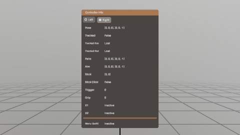
Controllers
While StereoKit prioritizes hand input, sometimes a controller has more precision! StereoKit provides access to any controllers via the Input.Controller function. This is a debug visualization of the controller data provided there.
StereoKit will simulate hands if only controllers are present, but it will not simulate controllers if only hands are present.
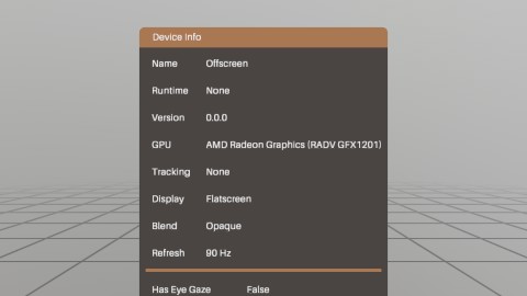
Device
The Device class contains a number of interesting bits of data about the device it’s running on! Most of this is just information, but there’s a few properties that can also be modified.
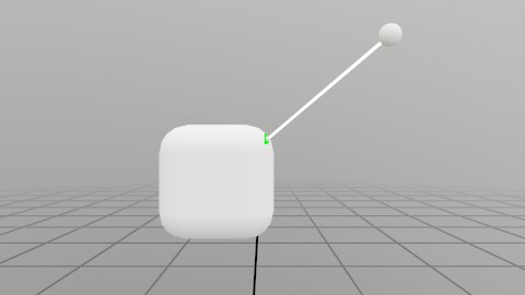
Eye Tracking
If the hardware supports it, and permissions are granted, eye tracking is as simple as grabbing Input.Eyes!
This scene is raycasting your eye ray at the indicated plane, and the dot’s red/green color indicates eye tracking availability! On flatscreen you can simulate eye tracking with Alt+Mouse.
![]()
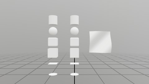
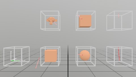
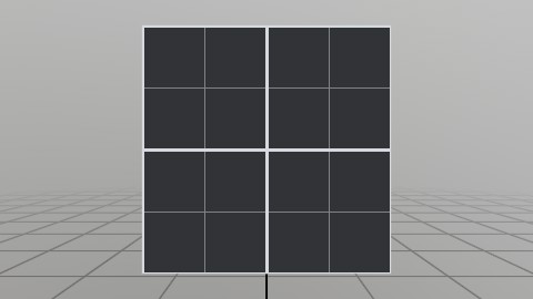
Mesh Generation
Generating a Mesh or Model via code can be an important task, and StereoKit provides a number of tools to make this pretty easy! In addition to the Default meshes, you can also generate a number of shapes, seen here. (See the Mesh.Gen functions)
If the provided shapes aren’t enough, it’s also pretty easy to procedurally assemble a mesh of your own from vertices and indices! That’s the wavy surface all the way to the right.
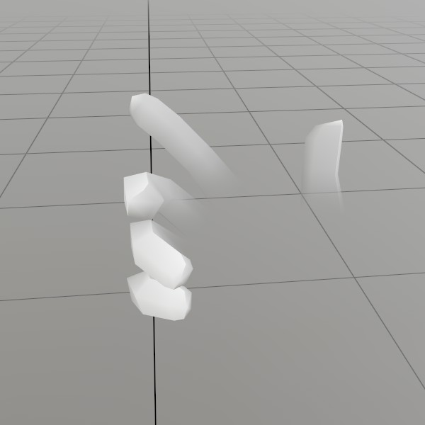
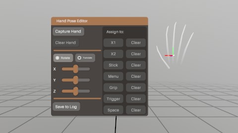
Hand Sim Poses
StereoKit simulates hand joints for controllers and mice, but sometimes you really just need to test a funky gesture!
The Input.HandSimPose functions allow you to customize how StereoKit simulates these hand poses, and this scene is a small tool to help you with capturing poses for these functions!
Hand Input
StereoKit uses a hands first approach to user input! Even when hand-sensors aren’t available, hand data is simulated instead using existing devices. Check out Input.Hand for all the cool data you get!
This demo is the source for the ‘Using Hands’ guide, and is a collection of different options and examples of how to get, use, and visualize Hand data.
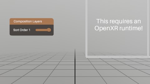
Composition Layers
OpenXR allows for a variety of surfaces to be composed onto the screen. StereoKit by default manages just a single ‘Projection Layer’, but you can also submit additional layers with special shapes (quad layers), or special color buffers (like video)!
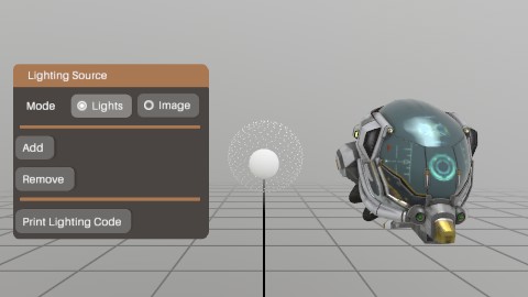
Lighting Editor
Line Render
Lines
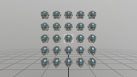
Many Objects
……
Materials
Material Chain
Materials can be chained together to create a multi-pass material! What you’re seeing in this sample is an ‘Inverted Shell’ outline, a two-pass effect where a second render pass is scaled along the normals and flipped inside-out.
Math
StereoKit has a SIMD optimized math library that provides a wide array of high-level math functions, shapes, and intersection formulas!
In C#, math types are backed by System.Numerics for easy interop with code from the rest of the C# ecosystem.
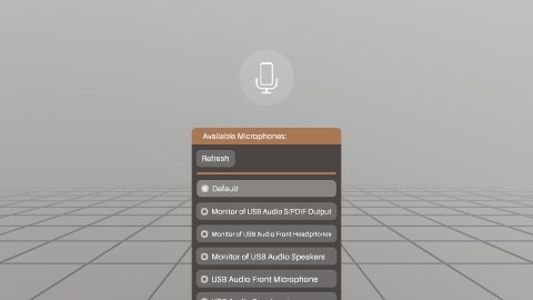
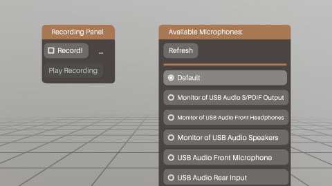
Microphone
Sometimes you need direct access to the microphone data! Maybe for a special effect, or maybe you just need to stream it to someone else. Well, there’s an easy API for that!
This demo shows how to grab input from the microphone, and use it to drive an indicator that tells users that you’re listening!
Model Nodes
ModelNode API lets…
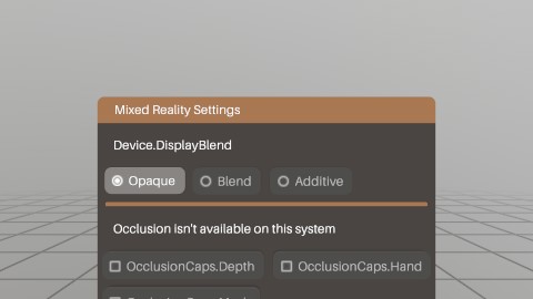
Mixed Reality
You can set up AR with OpenXR by changing the environment blend mode! In StereoKit, this is modifiable via Device.DisplayBlend at runtime, and SKSettings.blendPreference during initialization.
Note that some devices may not support each blend mode! Like a HoloLens can’t be Opaque, and some VR headsets can’t be transparent!
PBR Shaders
Shaders!
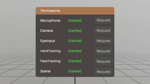
Permissions
StereoKit comes with APIs for managing cross-platform permissions. While on Desktop, permissions are almost not an issue, platforms like Android can get kinda complicated! Here, StereoKit provides an API that handles the more complicated permission issues of platforms like Android, and also can be a regular part of your desktop code!
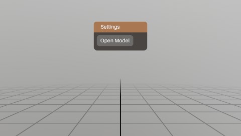
File Picker
Applications need to save and load files at runtime! StereoKit has a cross-platform, MR compatible file picker built in, Platform.FilePicker.
On systems/conditions where a native file picker is available, that’s what you’ll get! Otherwise, StereoKit will fall back to a custom picker built with StereoKit’s UI.
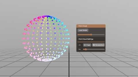
Point Clouds
Point clouds are not a built-in feature of StereoKit, but it’s not hard to do this yourself! Check out the code for this demo for a class that’ll help you do this directly from data, or from a Model.
Ray to Mesh
Record Mic
A common use case for the microphone would be to record a snippet of audio! This demo shows reading data from the Microphone, and using that to create a sound for playback.
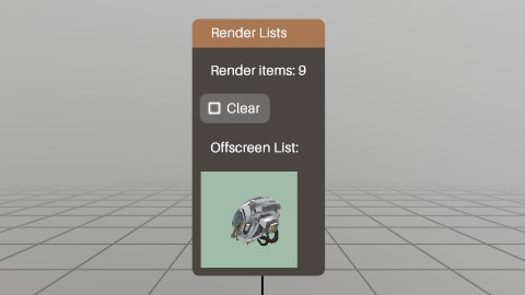
Render Lists
All draw calls are stored in RenderList.Primary, but you can also store your draw calls to custom RenderLists! This allows you to draw more specific scenes to render textures with greater control, for use as icons, thumbnails, and all sorts of interesting things!
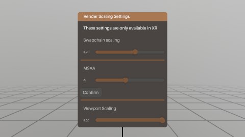
Render Scaling
Sometimes you need to boost the number of pixels your app renders, to reduce jaggies! Renderer.Scaling and Renderer.Multisample let you increase the size of the draw surface, and multisample each pixel.
This is powerful stuff, so use it sparingly!
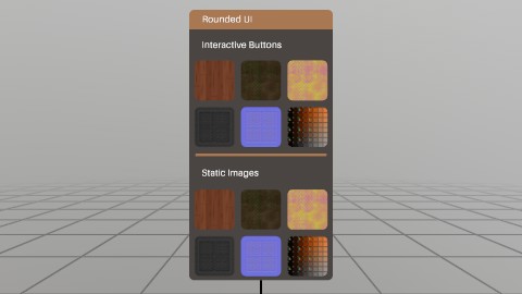
Rounded UI
Dynamic ShadowMaps
Using StereoKit’s Renderer.RenderTo, SetGlobalTexture, MaterialBuffers, and a bit of ingenuity, you can also add shadow mapping to your app!
This is a very basic single cascade implementation of shadow mapping to illustrate the idea.

Skeleton Estimation
With knowledge about where the head and hands are, you can make a decent guess about where some other parts of the body are! The StereoKit repository contains an AvatarSkeleton IStepper to show a basic example of how something like this can be done.
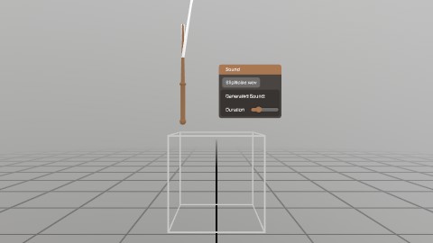
Sound
Text
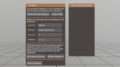
Text Input
Procedural Textures
Here’s a quick sample of procedurally assembling a texture!
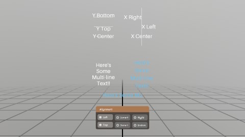
UI
…
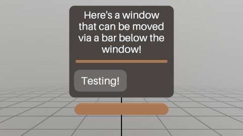
UI Grab Bar
This is an example of using external handles to manipulate a Window’s pose! Since you own the Pose data, you can do whatever you want with it! The grab bar below the window is a common sight to see in recent XR UI, so here’s one way to replicate that with SK’s API.
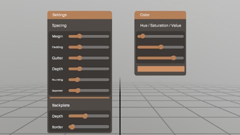
UI Settings
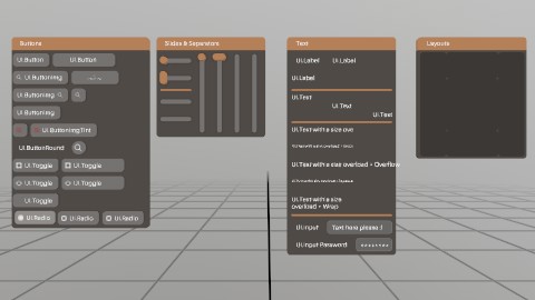
UI Tearsheet
An enumeration of all the different types of UI elements!
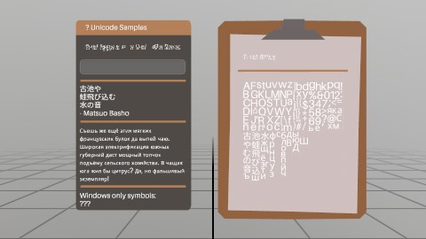
Unicode Text
Tools and Extensions
Tools and Extensions
Here’s a list of known tools designed to work with or extend StereoKit! If you’ve got something you’d like to see listed here, please file an Issue on the GitHub repository, we’d love to see it!
[NuGet] - Official - StereoKit.HolographicRemoting
This NuGet package is an implementation of HoloLens’ Holographic Remoting for StereoKit! This is an easy way to get desktop functionality onto your HoloLens, or cut down on iteration time while testing on-device.
[NuGet] - Official - StereoKit.DesktopMirror (Windows)
A small library for duplicating your desktop screen within a StereoKit application on Windows. Useful for developing in-context!
[GitHub] - Official (WIP) - StereoKit Browser
This is a short StereoKit sample that shows implementing a browser UI widget using CefSharp!
[GitHub] - StereoKit Tools Collection
A small collection of IStepper tools and utilities for StereoKit.
[GitHub] - StereoKit Light Bake
This is a quick demo for performantly managing static scenes, and baking lighting into them with StereoKit! This bakes lighting into the vertex colors of the mesh, so is visually limited by the number of vertices the mesh has, and will merge meshes together.
Examples
Anim.Duration
Loading an animated Model
Here, we’re loading a Model that we know has the animations “Idle” and “Jump”. This sample shows some options, but only a single call to PlayAnim is necessary to start an animation.
Model model = Model.FromFile("Cosmonaut.glb");

// You can look at the model's animations:
foreach (Anim anim in model.Anims)
	Log.Info($"Animation: {anim.Name} {anim.Duration}s");

// You can play an animation like this
model.PlayAnim("Jump", AnimMode.Once);

// Or you can find and store the animations in advance
Anim jumpAnim = model.FindAnim("Idle");
if (jumpAnim != null)
	model.PlayAnim(jumpAnim, AnimMode.Loop);
Anim.Name
See Anim.Duration
Anim.Name
Animation progress bar
A really simple progress bar visualization for the Model’s active animation.
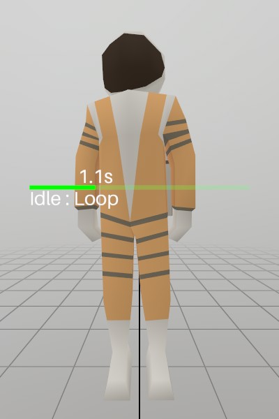
model.Draw(Matrix.Identity);

Hierarchy.Push(Matrix.T(0.5f, 1, -.25f));

// This is a pair of green lines that show the current progress through
// the animation.
float progress = model.AnimCompletion;
Lines.Add(V.XY0(0, 0), V.XY0(-progress, 0),  new Color(0,1,0,1.0f), 2*U.cm);
Lines.Add(V.XY0(-progress, 0), V.XY0(-1, 0), new Color(0,1,0,0.2f), 2*U.cm);

// These are some labels for the progress bar that tell us more about
// the active animation.
Text.Add($"{model.ActiveAnim.Name} : {model.AnimMode}", Matrix.TS(0, -2*U.cm, 0, 3),        Pivot.TopLeft);
Text.Add($"{model.AnimTime:F1}s",                       Matrix.TS(-progress, 2*U.cm, 0, 3), Pivot.BottomCenter);

Hierarchy.Pop();
Anim
See Anim.Duration
AnimMode
See Anim.Duration
AppFocus
Checking for changes in application focus
static AppFocus lastFocus = AppFocus.Hidden;
static void CheckFocus()
{
	if (lastFocus != SK.AppFocus)
	{
		lastFocus = SK.AppFocus;
		Log.Info($"App focus changed to: {lastFocus}");
	}
}
Assets.All
Enumerating all Assets
With Assets.All, you can take a peek at all the currently loaded Assets! Here’s a quick example of iterating through all assets and dumping a quick summary to the log.
foreach (var asset in Assets.All)
	Log.Info($"{asset.GetType().Name,-10} - {asset.Id}");
Assets.Type
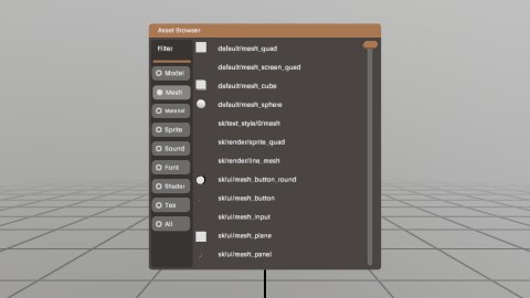
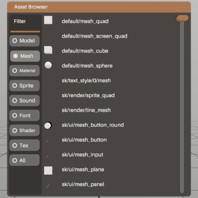
Simple Asset Browser
A full asset browser might have a few more features, but here’s a quick and dirty window that will provide a filtered list of the current live assets!
List<IAsset> filteredAssets = new List<IAsset>();
Type         filterType     = typeof(IAsset);
Pose         filterWindow   = Demo.contentPose.Pose;
float        filterScroll   = 0;
const int    filterScrollCt = 12;

void UpdateFilter(Type type)
{
	filterType   = type;
	filterScroll = 0.0f;
	filteredAssets.Clear();

	// Here's where the magic happens! `Assets.Type` can take a Type, or a
	// generic <T>, and will give a list of all assets that match that
	// type!
	filteredAssets.AddRange(Assets.Type(filterType));
}

public void AssetWindow()
{
	UISettings settings = UI.Settings;
	float height = filterScrollCt * (UI.LineHeight + settings.gutter) + settings.margin * 2;
	UI.WindowBegin("Asset Browser", ref filterWindow, V.XY(0.5f, height));

	UI.LayoutPushCut(UICut.Left, 0.08f);
	UI.PanelAt(UI.LayoutAt, UI.LayoutRemaining);

	UI.Label("Filter");

	UI.HSeparator();

	// A radio button selection for what to filter by
	Vec2 size = new Vec2(0.08f, 0);
	if (UI.Radio("Model",    filterType == typeof(Model   ), size)) UpdateFilter(typeof(Model));
	UI.SameLine();
	if (UI.Radio("Mesh",     filterType == typeof(Mesh    ), size)) UpdateFilter(typeof(Mesh));
	UI.SameLine();
	if (UI.Radio("Material", filterType == typeof(Material), size)) UpdateFilter(typeof(Material));
	UI.SameLine();
	if (UI.Radio("Sprite",   filterType == typeof(Sprite  ), size)) UpdateFilter(typeof(Sprite));
	UI.SameLine();
	if (UI.Radio("Sound",    filterType == typeof(Sound   ), size)) UpdateFilter(typeof(Sound));
	UI.SameLine();
	if (UI.Radio("Font",     filterType == typeof(Font    ), size)) UpdateFilter(typeof(Font));
	UI.SameLine();
	if (UI.Radio("Shader",   filterType == typeof(Shader  ), size)) UpdateFilter(typeof(Shader));
	UI.SameLine();
	if (UI.Radio("Tex",      filterType == typeof(Tex     ), size)) UpdateFilter(typeof(Tex));
	UI.SameLine();
	if (UI.Radio("All",      filterType == typeof(IAsset  ), size)) UpdateFilter(typeof(IAsset));

	UI.LayoutPop();

	UI.LayoutPushCut(UICut.Right, UI.LineHeight);
	UI.VSlider("scroll", ref filterScroll, 0, Math.Max(0,filteredAssets.Count-3), 1, 0, UIConfirm.Pinch);
	UI.LayoutPop();


	// We can visualize some of these assets, and just draw a label for
	// some others.
	for (int i = (int)filterScroll; i < Math.Min(filteredAssets.Count, (int)filterScroll + filterScrollCt); i++)
	{
		IAsset asset = filteredAssets[i];
		UI.PushId(i);
		switch (asset)
		{
			case Mesh     item: VisualizeMesh    (item); break;
			case Material item: VisualizeMaterial(item); break;
			case Sprite   item: VisualizeSprite  (item); break;
			case Model    item: VisualizeModel   (item); break;
			case Sound    item: VisualizeSound   (item); break;
		}
		UI.PopId();
		UI.Label(string.IsNullOrEmpty(asset.Id) ? "(null)" : asset.Id, V.XY(UI.LayoutRemaining.x, 0));
	}

	UI.WindowEnd();
}

void VisualizeMesh(Mesh item)
{
	Bounds meshSize = item.Bounds;
	Bounds b        = UI.LayoutReserve(V.XX(UI.LineHeight), false, UI.LineHeight);
	float  scale    = (1.0f/meshSize.dimensions.Length);
	item.Draw(Material.Default, Matrix.TS(b.center+meshSize.center*scale, b.dimensions*scale));

	UI.SameLine();
}

void VisualizeMaterial(Material item)
{
	// Default Materials have a number of special effect shaders that don't
	// visualize in a generic way.
	if (!string.IsNullOrEmpty(item.Id) && (item.Id.StartsWith("render/") || item.Id.StartsWith("default/")))
		return;

	Bounds b = UI.LayoutReserve(V.XX(UI.LineHeight), false, UI.LineHeight);
	Mesh.Sphere.Draw(item, Matrix.TS(b.center, b.dimensions));

	UI.SameLine();
}

void VisualizeSprite(Sprite item)
{
	UI.Image(item, V.XX(UI.LineHeight));
	UI.SameLine();
}

void VisualizeModel(Model item)
{
	UI.Model(item, V.XX(UI.LineHeight));
	UI.SameLine();
}

void VisualizeSound(Sound item)
{
	if (UI.ButtonImg(">", Sprite.ArrowRight, UIBtnLayout.CenterNoText, V.XX(UI.LineHeight)))
		item.Play(Hierarchy.ToWorld(UI.LayoutLast.center));
	UI.SameLine();
}
Assets.Type
See Assets.Type
Assets
See Assets.Type
Assets
See Assets.All
Backend.Graphics
Requesting Vulkan Extensions
StereoKit renders with Vulkan, and Backend.Vulkan lets you opt into extra
Vulkan instance/device extensions and device features that StereoKit
wouldn’t normally request. Register a BackendVulkanRequest before
SK.Initialize, then after initialization check whether it enabled and
resolve any functions it provides.
A good practical use is VK_EXT_debug_utils, which lets you attach
human-readable names to Vulkan objects so they show up nicely in tools like
RenderDoc or the validation layers. Here we request the (instance)
extension, then use it to name the VkDevice StereoKit is rendering with.
This is implemented via an IStepper, so it must be added before
SK.Initialize.
class VulkanDebugNamesExt : IStepper
{
	const string debugUtilsExt = "VK_EXT_debug_utils";

	// A C# equivalent of vkSetDebugUtilsObjectNameEXT and the struct it takes.
	[StructLayout(LayoutKind.Sequential)]
	struct VkDebugUtilsObjectNameInfoEXT
	{
		public int    sType;
		public IntPtr pNext;
		public int    objectType;
		public ulong  objectHandle;
		[MarshalAs(UnmanagedType.LPUTF8Str)] public string pObjectName;
	}
	delegate int VkSetDebugUtilsObjectNameEXT(IntPtr device, in VkDebugUtilsObjectNameInfoEXT nameInfo);
	static        VkSetDebugUtilsObjectNameEXT vkSetDebugUtilsObjectNameEXT;

	public bool Enabled { get; private set; }

	public VulkanDebugNamesExt()
	{
		// Vulkan requests must happen before StereoKit initializes, so this
		// IStepper needs to be added _before_ `SK.Initialize`.
		if (SK.IsInitialized)
			Log.Err("Vulkan extensions must be requested before StereoKit is initialized!");

		// debug_utils is an _instance_ extension. A named request lets us query
		// it later, and leaving `required` false means SK still starts up if
		// the extension isn't available.
		Backend.Vulkan.Request(new BackendVulkanRequest {
			name               = "debug_utils",
			required           = false,
			instanceExtensions = new string[] { debugUtilsExt },
		});
	}

	public bool Initialize()
	{
		// Confirm we're on Vulkan, the extension enabled, and our function
		// bound. RequestEnabled("debug_utils") would also work here.
		Enabled =
			Backend.Graphics == BackendGraphics.Vulkan &&
			Backend.Vulkan.ExtEnabled(debugUtilsExt)   &&
			LoadBindings();

		if (Enabled)
		{
			// Give the VkDevice a friendly name for debugging tools.
			VkDebugUtilsObjectNameInfoEXT info = new VkDebugUtilsObjectNameInfoEXT {
				sType        = 1000128000, // VK_STRUCTURE_TYPE_DEBUG_UTILS_OBJECT_NAME_INFO_EXT
				objectType   = 3,          // VK_OBJECT_TYPE_DEVICE
				objectHandle = (ulong)Backend.Vulkan.Device,
				pObjectName  = "StereoKit Device",
			};
			vkSetDebugUtilsObjectNameEXT(Backend.Vulkan.Device, info);
		}
		return Enabled;
	}

	private bool LoadBindings()
	{
		vkSetDebugUtilsObjectNameEXT = Backend.Vulkan.GetFunction<VkSetDebugUtilsObjectNameEXT>("vkSetDebugUtilsObjectNameEXT");
		return vkSetDebugUtilsObjectNameEXT != null;
	}

	public void Shutdown() { }
	public void Step() { }
}
Backend.XRType
Implementing OpenXR Extensions
Using the Backend.OpenXR class, it’s possible to implement OpenXR
extensions without directly modifying StereoKit! Here’s a simple
example of how to do this, implemented via an IStepper.
class Win32PerformanceCounterExt : IStepper
{
	// Start by defining C# equivalents of OpenXR's function signatures and
	// types. This can be a bit involved, see PassthroughFBExt.cs in the SK
	// repository for a more extensive sample.
	delegate uint XR_xrConvertTimeToWin32PerformanceCounterKHR(ulong instance, long time, out long performanceCounter);
	static        XR_xrConvertTimeToWin32PerformanceCounterKHR xrConvertTimeToWin32PerformanceCounterKHR;
	const string timeExt = "XR_KHR_win32_convert_performance_counter_time";

	public bool Enabled { get; private set; }

	public Win32PerformanceCounterExt()
	{
		// OpenXR extensions must be requested before initializing StereoKit,
		// so this IStepper needs to be added _before_ `SK.Initialize`.
		if (SK.IsInitialized)
			Log.Err("OpenXR extensions must be constructed before StereoKit is initialized!");

		// At this point, we don't even know if the app will have access to
		// OpenXR, so this should _not_ be be guarded by a check for OpenXR.
		Backend.OpenXR.RequestExt(timeExt);
	}

	public bool Initialize()
	{
		// Check if we're running OpenXR, the extension is present, and all of
		// our extension functions bound properly.
		Enabled =
			Backend.XRType == BackendXRType.OpenXR &&
			Backend.OpenXR.ExtEnabled(timeExt)     &&
			LoadBindings();

		// Test it out!
		if (Enabled)
		{
			xrConvertTimeToWin32PerformanceCounterKHR(Backend.OpenXR.Instance, Backend.OpenXR.Time, out long counter);
			Log.Info($"XrTime: {counter}");
		}

		return Enabled;
	}

	// In this method, we load any functions from the extension that we care
	// about, and then report if they were loaded successfully.
	private bool LoadBindings()
	{
		xrConvertTimeToWin32PerformanceCounterKHR =
			Backend.OpenXR.GetFunction<XR_xrConvertTimeToWin32PerformanceCounterKHR>("xrConvertTimeToWin32PerformanceCounterKHR");

		return xrConvertTimeToWin32PerformanceCounterKHR != null;
	}

	// A more complicated extension might use these, but this EXT does not
	// require any actions on-Step.
	public void Shutdown() { }
	public void Step() { }
}
Backend.OpenXR.Instance
See Backend.XRType
Backend.OpenXR.Time
See Backend.XRType
Backend.OpenXR.ExtEnabled
See Backend.XRType
Backend.OpenXR.GetFunction
See Backend.XRType
Backend.OpenXR.RequestExt
See Backend.XRType
Backend.Vulkan
See Backend.Graphics
BackendVulkanRequest
See Backend.Graphics
Bounds.Contains
Here’s a small example of checking to see if a finger joint is inside a box, and drawing an axis gizmo when it is!
// A volume for checking inside of! 10cm on each side, at the origin
Bounds testArea = new Bounds(Vec3.One * 0.1f);

// This is a decent way to show we're working with both hands
for (int h = 0; h < (int)Handed.Max; h++)
{
	// Get the pose for the index fingertip
	Hand hand      = Input.Hand((Handed)h);
	Pose fingertip = hand[FingerId.Index, JointId.Tip].Pose;

	// Skip this hand if it's not tracked
	if (!hand.IsTracked) continue;

	// Draw the fingertip pose axis if it's inside the volume
	if (testArea.Contains(fingertip.position))
		Lines.AddAxis(fingertip);
}
Bounds.FromCorner
General Usage
// All these create bounds for a 1x1x1m cube around the origin!
Bounds bounds = new Bounds(Vec3.One);
bounds = Bounds.FromCorner(new Vec3(-0.5f, -0.5f, -0.5f), Vec3.One);
bounds = Bounds.FromCorners(
	new Vec3(-0.5f, -0.5f, -0.5f),
	new Vec3( 0.5f,  0.5f,  0.5f));

// Note that positions must be in a coordinate space relative to
// the bounds!
if (bounds.Contains(new Vec3(0,0.25f,0)))
	Log.Info("Super easy to check if something's in it!");

// Casting a ray at a bounds is trivial too, again, ensure
// coordinates are in the same space!
Ray ray = new Ray(Vec3.Up, -Vec3.Up);
if (bounds.Intersect(ray, out Vec3 at))
	Log.Info($"Bounds intersection at {at}"); // <0, 0.5f, 0>

// You can also scale a Bounds using the '*' operator overload,
// this is really useful if you're working with the Bounds of a
// Model that you've scaled. It will scale the center as well as
// the size!
bounds = bounds * 0.5f;

// Scale the current bounds reference using 'Scale'
bounds.Scale(0.5f);

// Scale the bounds by a Vec3
bounds = bounds * new Vec3(1, 10, 0.5f);
Bounds.FromCorners
See Bounds.FromCorner
Bounds.Intersect
See Bounds.FromCorner
Bounds
See Bounds.FromCorner
Bounds
An Interactive Model
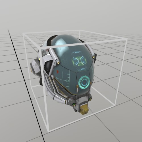
If you want to grab a Model and move it around, then you can use a
UI.Handle to do it! Here’s an example of loading a GLTF from file,
and using its information to create a Handle and a UI ‘cage’ box that
indicates an interactive element.
Model model      = Model.FromFile("DamagedHelmet.gltf");
Pose  handlePose = new Pose(0,0,0, Quat.Identity);
float scale      = .15f;

public void StepHandle() {
	UI.HandleBegin("Model Handle", ref handlePose, model.Bounds*scale);

	model.Draw(Matrix.S(scale));
	Mesh.Cube.Draw(Material.UIBox, Matrix.TS(model.Bounds.center*scale, model.Bounds.dimensions*scale));

	UI.HandleEnd();
}
BtnState
BtnState state = Input.Hand(Handed.Right).pinch;

// You can check a BtnState using bit-flag logic
if ((state & BtnState.Changed) > 0)
	Log.Info("Pinch state just changed!");

// Or you can check the same values with the extension methods, no
// bit flag logic :)
if (state.IsChanged())
	Log.Info("Pinch state just changed!");
BtnStateExtensions
See BtnState
Color.Hex
Creating color from hex values
Color   hex128 = Color  .Hex(0xFF0000FF); // Opaque Red
Color32 hex32  = Color32.Hex(0x00FF00FF); // Opaque Green
Color.HSV
// You can create a color using Red, Green, Blue, Alpha values,
// but it's often a great recipe for making a bad color.
Color color = new Color(1,0,0,1); // Red

// Hue, Saturation, Value, Alpha is a more natural way of picking
// colors. The commentdocs have a list of important values for Hue,
// to make it a little easier to pick the hue you want.
color = Color.HSV(0, 1, 1, 1); // Red

// And there's a few static colors available if you need 'em.
color = Color.White;

// You can also implicitly convert Color to a Color32!
Color32 color32 = color;
Color.HSV
// Desaturating a color can be done quite nicely with the HSV
// functions
Color red      = new Color(1,0,0,1);
Vec3  colorHSV = red.ToHSV();
colorHSV.y *= 0.5f; // Drop saturation by half
Color desaturatedRed = Color.HSV(colorHSV, red.a);

// LAB color space is excellent for modifying perceived
// brightness, or 'Lightness' of a color.
Color green    = new Color(0,1,0,1);
Vec3  colorLAB = green.ToLAB();
colorLAB.x *= 0.5f; // Drop lightness by half
Color darkGreen = Color.LAB(colorLAB, green.a);
Color.LAB
See Color.HSV
Color.ToHSV
See Color.HSV
Color.ToLAB
See Color.HSV
Color
See Color.HSV
Color
See Color.Hex
Color32.Hex
See Color.Hex
Color32
// You can create a color using Red, Green, Blue, Alpha values,
// but it's often a great recipe for making a bad color.
Color32 color = new Color32(255, 0, 0, 255); // Red

// Hue, Saturation, Value, Alpha is a more natural way of picking
// colors. You can use Color's HSV function, plus the implicit
// conversion to make a Color32!
color = Color.HSV(0, 1, 1, 1); // Red

// And there's a few static colors available if you need 'em.
color = Color32.White;
Color32
See Color.Hex
Controller.aim
Controller Debug Visualizer
This function shows a debug visualization of the current state of the controller! It’s not something you’d show to users, but it’s nice for just seeing how the API works, or as a temporary visualization.
void ShowController(Handed hand)
{
	bool      isLeft = hand == Handed.Left;
	PoseState state  = Input.PoseState(isLeft ? InputPose.LGrip : InputPose.RGrip);
	if (!state.IsTracked()) return;

	Hierarchy.Push(Input.Pose(isLeft?InputPose.LGrip:InputPose.RGrip));
		// Pick the controller color based on trackin info state
		Color color = Color.Black;
		if ((state & PoseState.PosInferred) > 0) color.g = 0.5f;
		if ((state & PoseState.PosKnown   ) > 0) color.g = 1;
		if ((state & PoseState.RotInferred) > 0) color.b = 0.5f;
		if ((state & PoseState.RotKnown   ) > 0) color.b = 1;
		Default.MeshCube.Draw(Default.Material, Matrix.S(new Vec3(3, 3, 8) * U.cm), color);

		// Show button info on the back of the controller
		Hierarchy.Push(Matrix.TR(0,1.6f*U.cm,0, Quat.LookAt(Vec3.Zero, new Vec3(0,1,0), new Vec3(0,0,-1))));

			// Show the tracking states as text
			Text.Add(state.IsPosKnown()?"(pos)":(state.IsPosInferred()?"~pos~":"pos"), Matrix.TS(0,-0.03f,0, 0.25f));
			Text.Add(state.IsRotKnown()?"(rot)":(state.IsRotInferred()?"~rot~":"rot"), Matrix.TS(0,-0.02f,0, 0.25f));

			// Show the controller's buttons
			Text.Add(Input.Button(isLeft?InputButton.LMenu:InputButton.RMenu).IsActive()?"(menu)":"menu", Matrix.TS(0,-0.01f,0, 0.25f));
			Text.Add(Input.Button(isLeft?InputButton.LX1  :InputButton.RX1  ).IsActive()?"(X1)":"X1", Matrix.TS(0,0.00f,0, 0.25f));
			Text.Add(Input.Button(isLeft?InputButton.LX2  :InputButton.RX2  ).IsActive()?"(X2)":"X2", Matrix.TS(0,0.01f,0, 0.25f));

			// Show the analog stick's information
			Vec3 stickAt = new Vec3(0, 0.03f, 0);
			Lines.Add(stickAt, stickAt + Input.XY(isLeft?InputXY.LStick:InputXY.RStick).XY0*0.01f, Color.White, 0.001f);
			if (Input.Button(isLeft?InputButton.LStick:InputButton.RStick).IsActive()) Text.Add("O", Matrix.TS(stickAt, 0.25f));

			// And show the trigger and grip buttons
			float trigger = Input.Float(isLeft?InputFloat.LTrigger:InputFloat.RTrigger);
			float grip    = Input.Float(isLeft?InputFloat.LGrip   :InputFloat.RGrip   );
			Default.MeshCube.Draw(Default.Material, Matrix.TS(0, -0.015f, -0.005f, new Vec3(0.01f, 0.04f, 0.01f)) * Matrix.TR(new Vec3(0,0.02f,0.03f), Quat.FromAngles(-45+trigger*40, 0,0) ));
			Default.MeshCube.Draw(Default.Material, Matrix.TS(0.0149f*(hand == Handed.Right?1:-1), 0, 0.015f, new Vec3(0.01f*(1-grip), 0.04f, 0.01f)));

		Hierarchy.Pop();
	Hierarchy.Pop();

	// And show the pointer
	Default.MeshCube.Draw(Default.Material, Input.Pose(isLeft?InputPose.LAim:InputPose.RAim).ToMatrix(new Vec3(1,1,4) * U.cm), Color.HSV(0,0.5f,0.8f).ToLinear());
}
Controller.grip
See Controller.aim
Controller.IsStickClicked
See Controller.aim
Controller.IsTracked
See Controller.aim
Controller.IsX1Pressed
See Controller.aim
Controller.IsX2Pressed
See Controller.aim
Controller.pose
See Controller.aim
Controller.stick
See Controller.aim
Controller.trackedPos
See Controller.aim
Controller.trackedRot
See Controller.aim
Controller.trigger
See Controller.aim
Controller
See Controller.aim
Cull.Front
Here’s setting FaceCull to Front, which is the opposite of the default behavior. On a sphere, this is a little hard to see, but you might notice here that the lighting is for the back side of the sphere!
matCull = Material.Default.Copy();
matCull.FaceCull = Cull.Front;
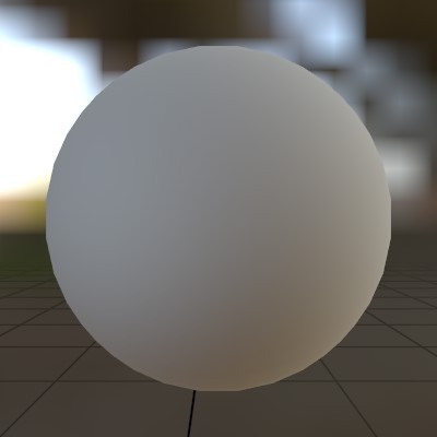
Default.Material
If you want to modify the default material, it’s recommended to copy it first!
matDefault = Material.Default.Copy();
And here’s what it looks like:
Default.MaterialPBR
Occlusion (R), Roughness (G), and Metal (B) are stored respectively in the R, G and B channels of their texture. Occlusion can be separated out into a different texture as per the GLTF spec, so you do need to assign it separately from the Metal texture.
matPBR = Material.PBR.Copy();
matPBR[MatParamName.DiffuseTex  ] = Tex.FromFile("metal_plate_diff.jpg");
matPBR[MatParamName.MetalTex    ] = Tex.FromFile("metal_plate_metal.jpg", false);
matPBR[MatParamName.OcclusionTex] = Tex.FromFile("metal_plate_metal.jpg", false);
Default.MaterialUI
This Material is basically the same as Default.Material, except it also adds some glow to the surface near the user’s fingers. It works best on flat surfaces, and in StereoKit’s design language, can be used to indicate that something is interactive.
matUI = Material.UI.Copy();
And here’s what it looks like:
Default.MaterialUIBox
The UI Box material has 3 parameters to control how the box wires are rendered. The initial size in meters is ‘border_size’, and can grow by ‘border_size_grow’ meters based on distance to the user’s hand. That distance can be configured via the ‘border_affect_radius’ property of the shader, which is also in meters.
matUIBox = Material.UIBox.Copy();
matUIBox["border_size"]          = 0.005f;
matUIBox["border_size_grow"]     = 0.01f;
matUIBox["border_affect_radius"] = 0.2f;
Default.MaterialUnlit
matUnlit = Material.Unlit.Copy();
matUnlit[MatParamName.DiffuseTex] = Tex.FromFile("floor.png");
FingerId
See Bounds.Contains
Font.FromFile
Drawing text with and without a TextStyle
 We can use a TextStyle object to control how text gets displayed!
TextStyle style;
Font.FromFile
In initialization, we can create the style from a font, a size, and a base color. Overloads for MakeStyle can allow you to override the default font shader, or provide a specific Material.
style = Text.MakeStyle(
	Font.FromFile("aileron_font.ttf"),
	2 * U.cm,
	Color.HSV(0.55f, 0.62f, 0.93f));
Font.FromFile
Then it’s pretty trivial to just draw some text on the screen! Just call Text.Add on update. If you don’t have a TextStyle available, calling it without one will just fall back on the default style.
// Text with an explicit text style
Text.Add(
	"Here's\nSome\nMulti-line\nText!!",
	Matrix.TR(new Vec3(0.1f, 0, 0), Quat.LookDir(0, 0, 1)),
	style);
// Text using the default text style
Text.Add(
	"Here's\nSome\nMulti-line\nText!!",
	Matrix.TR(new Vec3(-0.1f, 0, 0), Quat.LookDir(0, 0, 1)));
Hand
See Bounds.Contains
Handed
See Bounds.Contains
Hierarchy.Pop
Transforming with Hierarchy
In StereoKit, draw calls all happen relative to the Hierarchy
stack! In this example, we make 2 draw calls with the same
transform matrix, but use the Hierarchy as a transform parent to
ensure the draws happen in different locations.
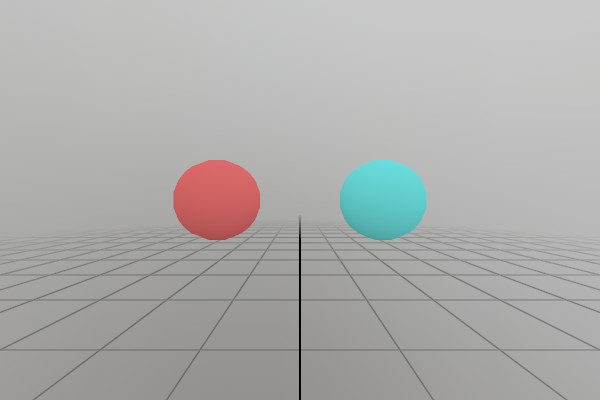
Push/Pop calls can also be nested to create more complex
hierarchies on a stack! Each Push call is also relative to the
parent Pushed transform.
Matrix transform = Matrix.S(0.2f);

Hierarchy.Push(Matrix.T(-0.2f, 0, -0.5f));
Mesh.Sphere.Draw(Material.Default, transform, Color.HSV(0.0f, .8f, .8f));
Hierarchy.Pop();

Hierarchy.Push(Matrix.T( 0.2f, 0, -0.5f));
Mesh.Sphere.Draw(Material.Default, transform, Color.HSV(0.5f, .8f, .8f));
Hierarchy.Pop();
One key thing to remember is that you should always match a
Popfor eachPush.
Hierarchy.Pop
Spaces and Intersections
One tricky thing you need to keep in mind when working with
different spaces like the ones created with Hierarchy is that any
values you use for math need to be in the same space! I like to
explicitly label my variables with the space they’re in anytime I’m
working with anything even a little complicated!
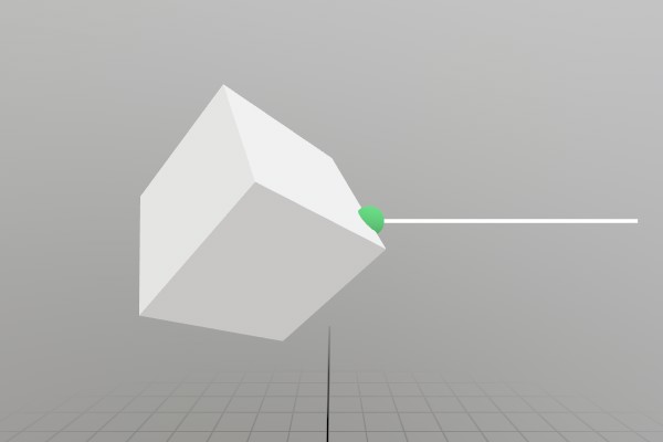
Here’s an example of intersecting a ray with some content that
exists inside of a Hierarchy stack. You always need to transform
your data into Mesh or Model space in order to do an
Intersect, but the Hierarchy here adds a bit of extra
complexity to the problem!
// It can often be helpful to consider if you're making a function
// "Hierarchy aware", meaning that it will still work properly if the
// code _already_ exists within a transformed hierarchy! Here we're
// using `Hierarchy.ToWorld` to ensure our intersection ray is
// _for sure_ in World Space.
Ray parentSpaceRay = new Ray(V.XYZ(0.5f, 4, -0.5f), V.XYZ(-1, 0, 0));
Ray worldSpaceRay  = Hierarchy.ToWorld(parentSpaceRay);
Lines.Add(parentSpaceRay, 0.5f, Color.White, 0.005f);

// Sometimes it can help with clarity to add scope brackets to show
// how the hierarchy is affecting the code!
Hierarchy.Push(Matrix.T(0, 4, -0.5f));
{
	Matrix localTransform = Matrix.TRS(Vec3.Zero, Quat.FromAngles(20, 135, 45), 0.2f);
	Mesh.Cube.Draw(Material.Default, localTransform);

	// Mesh intersection _must_ be done in Mesh space, since that's
	// the space the Vertex data is in. So we need to convert our
	// intersection ray all the way from world space to mesh space here
	// before calling `Intersect`!
	Ray localSpaceRay = Hierarchy.ToLocal(worldSpaceRay);
	Ray meshSpaceRay  = localTransform.Inverse.Transform(localSpaceRay);
	if (meshSpaceRay.Intersect(Mesh.Cube, out Ray meshSpaceAt))
	{
		// Similarly, the intersection point needs to be transformed
		// from Mesh space back into our local space before drawing it.
		Ray localAt = localTransform.Transform(meshSpaceAt);
		Mesh.Sphere.Draw(Material.Default, Matrix.TS(localAt.position, 0.04f), Color.HSV(0.36f, .8f, .8f));
	}
}
Hierarchy.Pop();
Hierarchy.Push
See Hierarchy.Pop
Hierarchy.Push
See Hierarchy.Pop
Hierarchy.ToLocal
See Hierarchy.Pop
Hierarchy.ToWorld
See Hierarchy.Pop
Hierarchy
See Hierarchy.Pop
Hierarchy
See Hierarchy.Pop
Input.ControllerMenuButton
See Controller.aim
Input.Eyes
if (Input.EyesTracked.IsActive())
{
	// Intersect the eye Ray with a floor plane
	Plane plane = new Plane(Vec3.Zero, Vec3.Up);
	if (Input.Eyes.Ray.Intersect(plane, out Vec3 at))
	{
		Default.MeshSphere.Draw(Default.Material, Matrix.TS(at, .05f));
	}
}
Input.EyesTracked
See Input.Eyes
Input.FingerGlow
Disabling Finger Glow
When using StereoKit’s built-in UI shaders, or the shader API’s
sk_finger_glow, StereoKit provides a glowing aura around the
pointer finger.
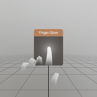
This feature is on by default, but can be disabled without
modifying shaders! As long as Input.FingerGlow is false at
the end of the frame, StereoKit will skip providing the shaders
with valid finger pose data for the glow effect.
Input.FingerGlow = false;
Input.Controller
See Controller.aim
Input.Hand
See Bounds.Contains
Input.HapticCaps
Driving haptics from controller velocity
This shows how to map a continuous physical signal (here, the
controller’s grip-pose velocity) onto haptic output. There are two
paths: a simple per-frame HapticPulse that works on every device,
and a streaming HapticWaveform path that’s used when
XR_FB_haptic_pcm is available.
void StepProcedural(InputHaptic output)
{
	Handed   hand    = output == InputHaptic.LController ? Handed.Left : Handed.Right;
	InputPose pose   = output == InputHaptic.LController ? InputPose.LGrip : InputPose.RGrip;
	PoseState state  = Input.PoseState(pose);
	if (!state.IsTracked()) { haveLastPos = false; return; }

	Vec3 pos = Input.Pose(pose).position;
	if (!haveLastPos) { lastGripPos = pos; haveLastPos = true; return; }

	float speed   = (pos - lastGripPos).Length / Math.Max(0.001f, Time.Stepf);
	lastGripPos   = pos;
	float intensity = MathF.Min(1, speed / 2.0f); // ~2 m/s saturates

	InputHapticCaps caps = Input.HapticCaps(output);
	if ((caps & InputHapticCaps.Waveform) != 0)
	{
		// Streaming path: synthesize one frame's worth of samples at the
		// device's preferred rate, append onto the existing stream.
		float r     = Input.HapticPreferredRate(output);
		if (r <= 0) r = 4000;
		int   count = (int)(r * Time.Stepf);
		if (procBuffer.Length != count) procBuffer = new float[count];
		for (int i = 0; i < count; i++)
			procBuffer[i] = MathF.Sin(2 * MathF.PI * 220 * i / r) * intensity;
		Input.HapticWaveform(output, procBuffer, r, append: true);
	}
	else if ((caps & InputHapticCaps.Pulse) != 0)
	{
		// Fallback path: per-frame pulse with current intensity.
		Input.HapticPulse(output, 0, intensity, Time.Stepf);
	}
}
Input.HapticPreferredRate
See Input.HapticCaps
Input.HapticPulse
See Input.HapticCaps
Input.HapticStop
See Input.HapticCaps
Input.HapticWaveform
See Input.HapticCaps
Input.TextConsume
Raw Text Input
// If you need to read text input directly from a soft or hard keyboard,
// these functions give you direct access to the stream of Unicode
// characters produced! These characters are language and keyboard layout
// sensitive, making these functions the correct ones for working with text
// content vs. the `Input.Key` functions, which are not language specific.
//
// Every frame, `Input.TextConsume` will have a list of new characters that
// have been pressed or submitted to the app. Reading them will "consume"
// them, making them unavailable to anything that comes after. If you need
// to bypass some earlier element consuming them, you can reset the current
// frame's consume queue with `Input.TextReset`.
Pose         rawWinPose = new Pose(0.3f,0,0);
List<string> uniChars   = new List<string>(Enumerable.Repeat("", 10));
void ShowRawInputWindow()
{
	UI.WindowBegin("Raw keyboard code points:", ref rawWinPose);

	// Reset the text input back to the start of the list, since any
	// UI.Input before this will consume the characters first and we
	// always want to show input on this window.
	Input.TextReset();

	while (true)
	{
		// Consume each new character, 0 marks the end of the list of new
		// characters.
		char c = Input.TextConsume();
		if (c == 0) break;

		// Insert the codepoint at the start of the list, and bump off any
		// more than 10 items.
		uniChars.Insert(0, $"{(int)c}");
		if (uniChars.Count > 10)
			uniChars.RemoveAt(uniChars.Count - 1);
	}

	// Show each character code as a label
	for (int i = 0; i < uniChars.Count; i++)
		UI.Label(uniChars[i]);

	UI.WindowEnd();
}
Input.TextReset
See Input.TextConsume
JointId
See Bounds.Contains
Lines.Add
Lines.Add(new Vec3(0.1f,0,0), new Vec3(-0.1f,0,0), Color.White, 0.01f);
Lines.Add
Lines.Add(new Vec3(0.1f,0,0), new Vec3(-0.1f,0,0), Color.White, Color.Black, 0.01f);
Lines.Add
Lines.Add(new LinePoint[]{
	new LinePoint(new Vec3( 0.1f, 0,     0), Color.White, 0.01f),
	new LinePoint(new Vec3( 0,    0.02f, 0), Color.Black, 0.005f),
	new LinePoint(new Vec3(-0.1f, 0,     0), Color.White, 0.01f),
});
Lines.AddAxis
See Bounds.Contains
Lines.AddAxis
Identity Pose
The identity pose is a Pose at (0,0,0) facing Forward, which in
StereoKit is a direction of (0,0,-1) represented by a Quaternion of
(0,0,0,1). Note that a Quaternion of (0,0,0,0) is invalid, and can
cause problems with math, so using default or an empty
new Pose() with this struct can result in bad math results.
Pose.Identity is a good default to get used to!
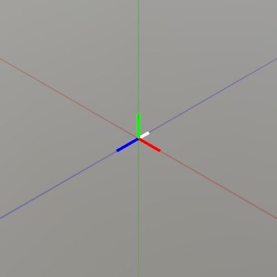
Note that Lines.AddAxis here shows the Pose orientation by
drawing the pose local X+ (red) Y+ (blue) Z+ (green) axis lines in
the positive direction, and Forward in white.
Pose pose = Pose.Identity;
Lines.AddAxis(pose);

// Show the origin for clarity
Lines.Add(V.XYZ(-1,0,0), V.XYZ(1,0,0), new Color32(100,0,0,100), 0.0005f);
Lines.Add(V.XYZ(0,-1,0), V.XYZ(0,1,0), new Color32(0,100,0,100), 0.0005f);
Lines.Add(V.XYZ(0,0,-1), V.XYZ(0,0,1), new Color32(0,0,100,100), 0.0005f);
Lines
See Lines.AddAxis
Log.Filter
Show everything that StereoKit logs!
Log.Filter = LogLevel.Diagnostic;
Or, only show warnings and errors:
Log.Filter = LogLevel.Warning;
Log.Diag
Log.Diag($"<~blu>{Time.Total:0.0}s<~clr> have elapsed since StereoKit start.");
Log.Err
if (Time.Stepf > 0.017f)
	Log.Err($"Oh no! Frame time (<~red>{Time.Stepf}<~clr>) has exceeded 17ms! There's no way we'll hit even 60 frames per second!");
Log.Info
Log.Info($"<~grn>{Time.Total:0.0}s<~clr> have elapsed since StereoKit start.");
Log.Subscribe
Then you add the OnLog method into the log events like this in your initialization code!
Log.Subscribe(OnLog);
Log.Subscribe
And in your Update loop, you can draw the window.
LogWindow();
And that’s it!
Log.Subscribe
An in-application log window
Here’s an example of using the Log.Subscribe method to build a simple logging window. This can be pretty handy to have around somewhere in your application!
Here’s the code for the window, and log tracking.
static Pose logPose = new Pose(0, -0.1f, 0.5f, Quat.LookDir(Vec3.Forward));
static List<string> logList = new List<string>();
static float logIndex = 0;
static string logString = "";
static void OnLog(LogLevel level, string text)
{
	logList.Insert(0, text.Length < 100 ? text + "\n" : text.Substring(0, 100) + "...\n");
	UpdateLogStr((int)logIndex);
}

static void UpdateLogStr(int index)
{
	logIndex = Math.Max(Math.Min(index, logList.Count - 1), 0);
	logString = "";
	for (int i = index; i < index + 15 && i < logList.Count; i++)
		logString += logList[i];
}

static void LogWindow()
{
	UI.WindowBegin("Log", ref logPose, new Vec2(40, 0) * U.cm);

	UI.LayoutPushCut(UICut.Right, UI.LineHeight);
	if (UI.VSlider("scroll", ref logIndex, 0, Math.Max(logList.Count - 3, 0), 1))
		UpdateLogStr((int)logIndex);
	UI.LayoutPop();

	UI.Text(logString);
	UI.WindowEnd();
}
Log.Unsubscribe
LogCallback onLog = (LogLevel level, string logText)
	=> Console.WriteLine(logText);

Log.Subscribe(onLog);
…
Log.Unsubscribe(onLog);
Log.Warn
Log.Warn($"Warning! <~ylw>{Time.Total:0.0}s<~clr> have elapsed since StereoKit start!");
Log.Write
Log.Write(LogLevel.Info, $"<~grn>{Time.Total:0.0}s<~clr> have elapsed since StereoKit start.");
Log
See Log.Subscribe
Log
See Log.Subscribe
Log
See Log.Subscribe
Material.Chain
Inverted Shell Chain
Materials can be chained together to create a multi-pass material! What you’re seeing here is an ‘Inverted Shell’ outline, a two-pass effect where a second render pass is scaled along the normals and flipped inside-out.
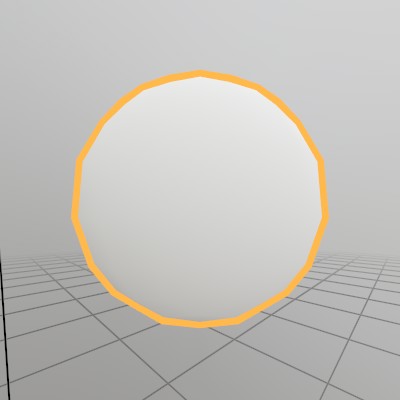
Material outlineMaterial;

void CreateShellMaterial()
{
	Material shellMaterial = new Material("inflatable.hlsl");
	shellMaterial.FaceCull = Cull.Front;
	shellMaterial[MatParamName.ColorTint] = Color.HSV(0.1f, 0.7f, 1);

	outlineMaterial = Material.Default.Copy();
	outlineMaterial.Chain = shellMaterial;
}

void DrawOutlineObject()
{
	Mesh.Sphere.Draw(outlineMaterial, Matrix.S(0.3f));
}
Material.Default
See Default.Material
Material.FaceCull
See Cull.Front
Material.ParamCount
Listing parameters in a Material
// Iterate using a foreach
Log.Info("Builtin PBR Materials contain these parameters:");
foreach (MatParamInfo info in Material.PBR.GetAllParamInfo())
	Log.Info($"- {info.type,8}: {info.name}");

// Or with a normal for loop
Log.Info("Builtin Unlit Materials contain these parameters:");
for (int i=0; i<Material.Unlit.ParamCount; i+=1)
{
	MatParamInfo info = Material.Unlit.GetParamInfo(i);
	Log.Info($"- {info.type,8}: {info.name}");
}
Material.PBR
See Default.MaterialPBR
Material.Transparency
Additive Transparency
Here’s an example material with additive transparency. Transparent materials typically don’t write to the depth buffer, but this may vary from case to case. Note that the material’s alpha does not play any role in additive transparency! Instead, you could make the material’s tint darker.
matAlphaAdd = Material.Default.Copy();
matAlphaAdd.Transparency = Transparency.Add;
matAlphaAdd.DepthWrite   = false;
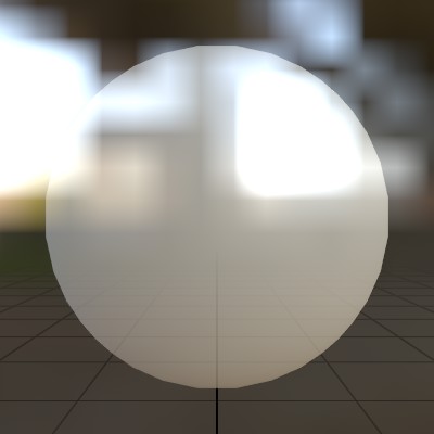
Material.Transparency
Alpha Blending
Here’s an example material with an alpha blend transparency. Transparent materials typically don’t write to the depth buffer, but this may vary from case to case. Here we’re setting the alpha through the material’s Tint value, but the diffuse texture’s alpha and the instance render color’s alpha may also play a part in the final alpha value.
matAlphaBlend = Material.Default.Copy();
matAlphaBlend.Transparency = Transparency.Blend;
matAlphaBlend.DepthWrite   = false;
matAlphaBlend[MatParamName.ColorTint] = new Color(1, 1, 1, 0.75f);

Material.Transparency
MSAA (Alpha to Coverage)
Here’s an example material with a transparency mode that utilizes MSAA samples for blending. Also known as Alpha To Coverage, this takes advantage of the fact that MSAA can generate multiple fragments per-pixel while utilizing the zbuffer, and then blend them together before presenting the image. This means you can dodge a couple of z-sorting artifacts, but with a limited/quantized number of transparency “values” equivalent to the number of MSAA samples.
matMSAABlend = Material.Default.Copy();
matMSAABlend.Transparency = Transparency.MSAA;
matMSAABlend[MatParamName.ColorTint] = new Color(1, 1, 1, 0.75f);
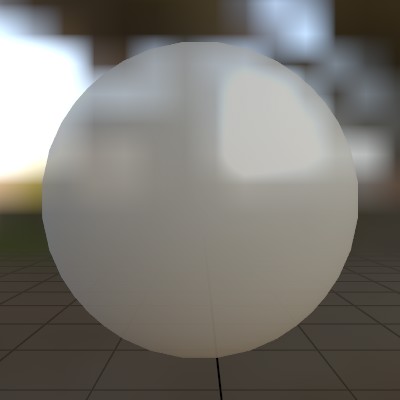
Material.UI
See Default.MaterialUI
Material.UIBox
See Default.MaterialUIBox
Material.UIBox
See Bounds
Material.Unlit
See Default.MaterialUnlit
Material.Wireframe
Here’s creating a simple wireframe material!
matWireframe = Material.Default.Copy();
matWireframe.Wireframe = true;
Which looks like this:
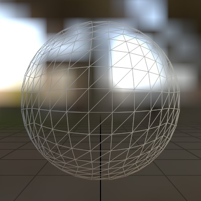
Material.Copy
Copying assets
Modifying an asset will affect everything that uses that asset! Often you’ll want to copy an asset before modifying it, to ensure other parts of your application look the same. In particular, modifying default assets is not a good idea, unless you do want to modify the defaults globally.
Model model1 = new Model(Mesh.Sphere, Material.Default);
model1.RootNode.LocalTransform = Matrix.S(0.1f);

Material mat = Material.Default.Copy();
mat[MatParamName.ColorTint] = new Color(1,0,0,1);
Model model2 = model1.Copy();
model2.RootNode.Material = mat;
Material.GetAllParamInfo
See Material.ParamCount
Material.GetParamInfo
See Material.ParamCount
Material.SetBool
Specialization constants
If a shader declares specialization constants with HLSL’s
[[vk::constant_id(N)]], StereoKit exposes them through the ordinary
scalar setters. The name you pass must match the HLSL variable name.
[[vk::constant_id(0)]] const int   COLOR_STEPS = 2;
[[vk::constant_id(1)]] const float BRIGHTNESS  = 0.25;
[[vk::constant_id(2)]] const bool  USE_TINT    = true;
[[vk::constant_id(3)]] const uint  BLUE_SCALE  = 4;
Unlike a normal material parameter, a spec constant is baked into the shader pipeline. Setting one to a new value rebuilds that pipeline (a heavier operation than a uniform write), so prefer setting them at load time rather than every frame. Re-setting the same value is free. Two materials sharing one shader with different spec-constant values are distinct pipeline variants — handy for feature toggles or loop/array sizes the driver can then fold at compile time.
Material variantA;
Material variantB;
public void Initialize()
{
	Shader shader = Shader.FromFile("spec_constant_test.hlsl");

	variantA = new Material(shader); // uses the HLSL defaults

	variantB = new Material(shader);
	variantB.SetInt  ("COLOR_STEPS", 4);
	variantB.SetFloat("BRIGHTNESS",  0.6f);
	variantB.SetBool ("USE_TINT",    false);
	variantB.SetUInt ("BLUE_SCALE",  12);
}
Material.SetData
Assigning an array in a Shader
This is a bit of a hack until proper shader support for arrays arrives, but with a few C# marshalling tricks, we can assign array without too much trouble. Look for improvements to this in later versions of SteroKit.
// This struct matches a shader parameter of `float4 offsets[10];`
[StructLayout(LayoutKind.Sequential)]
struct ShaderData
{
	[MarshalAs(UnmanagedType.ByValArray, SizeConst = 10)]
	public Vec4[] offsets;
}

Material arrayMaterial = null;
public void Initialize()
{
	ShaderData shaderData = new ShaderData();
	shaderData.offsets = new Vec4[10] {
		V.XYZW(0,0,0,0),
		V.XYZW(0.2f,0,0,0),
		V.XYZW(0.4f,0,0,0),
		V.XYZW(0.4f,0.2f,0,0),
		V.XYZW(0.4f,0.4f,0,0),
		V.XYZW(0.4f,0.6f,0,0),
		V.XYZW(0.2f,0.6f,0,0),
		V.XYZW(0,0.6f,0,0),
		V.XYZW(0,0.4f,0,0),
		V.XYZW(0,0.2f,0,0)};

	arrayMaterial = new Material(Shader.FromFile("shader_arrays.hlsl"));
	arrayMaterial[MatParamName.DiffuseTex] = Tex.FromFile("test.png");
	arrayMaterial.SetData<ShaderData>("offsets", shaderData);
}
Material.SetFloat
See Material.SetBool
Material.SetInt
See Material.SetBool
Material.SetUInt
See Material.SetBool
Material
Material parameter access
Material does have an array operator overload for setting shader parameters really quickly! You can do this with strings representing shader parameter names, or use the MatParamName enum for compile safety.
exampleMaterial[MatParamName.DiffuseTex  ] = gridTex;
exampleMaterial[MatParamName.TexTransform] = new Vec4(0,0,2,2);
Material
See Material.SetData
MatParamInfo.name
See Material.ParamCount
MatParamInfo.type
See Material.ParamCount
MatParamInfo
See Material.ParamCount
MatParamName
See Material
Mesh.Bounds
See Bounds
Mesh.IndCount
Counting the Vertices and Triangles in a Model
Model.Visuals are always guaranteed to have a Mesh, so no need to null check there, and VertCount and IndCount are available even if Mesh.KeepData is false!
int vertCount = 0;
int triCount  = 0;

foreach (ModelNode node in model.Visuals)
{
	Mesh mesh = node.Mesh;
	vertCount += mesh.VertCount;
	triCount  += mesh.IndCount / 3;
}
Log.Info($"Model stats: {vertCount} vertices, {triCount} triangles");
Mesh.VertCount
See Mesh.IndCount
Mesh.Draw
Generating a Mesh and Model
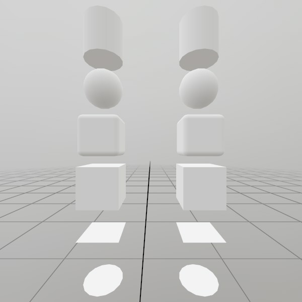
Here’s a quick example of generating a mesh! You can store it in just a Mesh, or you can attach it to a Model for easier rendering later on.
// Do this in your initialization
Mesh  roundedCubeMesh  = Mesh.GenerateRoundedCube(Vec3.One * 0.4f, 0.05f);
Model roundedCubeModel = Model.FromMesh(roundedCubeMesh, Default.Material);
Mesh.Draw
Drawing both a Mesh and a Model generated this way is reasonably simple, here’s a short example! For the Mesh, you’ll need to create your own material, we just loaded up the default Material here.
// Call this code every Step

Matrix roundedCubeTransform = Matrix.T(0, 0, 0);
roundedCubeMesh.Draw(Default.Material, roundedCubeTransform);

roundedCubeTransform = Matrix.T(1, 0, 0);
roundedCubeModel.Draw(roundedCubeTransform);
Mesh.GenerateCircle
Generating a Mesh and Model
Here’s a quick example of generating a mesh! You can store it in just a Mesh, or you can attach it to a Model for easier rendering later on.
// Do this in your initialization
Mesh  circleMesh  = Mesh.GenerateCircle(0.4f);
Model circleModel = Model.FromMesh(circleMesh, Default.Material);
Mesh.GenerateCircle
Drawing both a Mesh and a Model generated this way is reasonably simple, here’s a short example! For the Mesh, you’ll need to create your own material, we just loaded up the default Material here.
Matrix circleTransform = Matrix.T(0, -1.5f, 0);
circleMesh.Draw(Default.Material, circleTransform);

circleTransform = Matrix.T(1, -1.5f, 0);
circleModel.Draw(circleTransform);
Mesh.GenerateCircle
UV and Face layout
Here’s a test image that illustrates how this mesh’s geometry is
laid out.
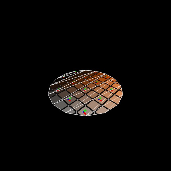
meshCircle = Mesh.GenerateCircle(1);
Mesh.GenerateCube
Generating a Mesh and Model
Here’s a quick example of generating a mesh! You can store it in just a Mesh, or you can attach it to a Model for easier rendering later on.
Mesh  cubeMesh  = Mesh.GenerateCube(Vec3.One * 0.4f);
Model cubeModel = Model.FromMesh(cubeMesh, Default.Material);
Mesh.GenerateCube
Drawing both a Mesh and a Model generated this way is reasonably simple, here’s a short example! For the Mesh, you’ll need to create your own material, we just loaded up the default Material here.
// Call this code every Step

Matrix cubeTransform = Matrix.T(0, -.5f, 0);
cubeMesh.Draw(Default.Material, cubeTransform);

cubeTransform = Matrix.T(1, -.5f, 0);
cubeModel.Draw(cubeTransform);
Mesh.GenerateCube
UV and Face layout
Here’s a test image that illustrates how this mesh’s geometry is
laid out.
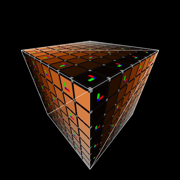
meshCube = Mesh.GenerateCube(Vec3.One);
Mesh.GenerateCylinder
Generating a Mesh and Model
Here’s a quick example of generating a mesh! You can store it in just a Mesh, or you can attach it to a Model for easier rendering later on.
// Do this in your initialization
Mesh  cylinderMesh  = Mesh.GenerateCylinder(0.4f, 0.4f, Vec3.Up);
Model cylinderModel = Model.FromMesh(cylinderMesh, Default.Material);
Mesh.GenerateCylinder
Drawing both a Mesh and a Model generated this way is reasonably simple, here’s a short example! For the Mesh, you’ll need to create your own material, we just loaded up the default Material here.
// Call this code every Step

Matrix cylinderTransform = Matrix.T(0, 1, 0);
cylinderMesh.Draw(Default.Material, cylinderTransform);

cylinderTransform = Matrix.T(1, 1, 0);
cylinderModel.Draw(cylinderTransform);
Mesh.GenerateCylinder
UV and Face layout
Here’s a test image that illustrates how this mesh’s geometry is
laid out.
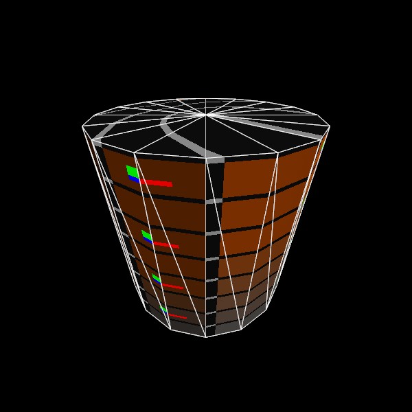
meshCylinder = Mesh.GenerateCylinder(1, 1, Vec3.Up);
Mesh.GeneratePlane
Generating a Mesh and Model
Here’s a quick example of generating a mesh! You can store it in just a Mesh, or you can attach it to a Model for easier rendering later on.
// Do this in your initialization
Mesh  planeMesh  = Mesh.GeneratePlane(Vec2.One*0.4f);
Model planeModel = Model.FromMesh(planeMesh, Default.Material);
Mesh.GeneratePlane
Drawing both a Mesh and a Model generated this way is reasonably simple, here’s a short example! For the Mesh, you’ll need to create your own material, we just loaded up the default Material here.
Matrix planeTransform = Matrix.T(0, -1, 0);
planeMesh.Draw(Default.Material, planeTransform);

planeTransform = Matrix.T(1, -1, 0);
planeModel.Draw(planeTransform);
Mesh.GeneratePlane
UV and Face layout
Here’s a test image that illustrates how this mesh’s geometry is
laid out.
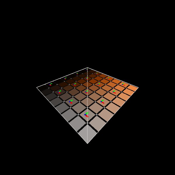
meshPlane = Mesh.GeneratePlane(Vec2.One);
Mesh.GenerateRoundedCube
See Mesh.Draw
Mesh.GenerateRoundedCube
See Mesh.Draw
Mesh.GenerateRoundedCube
UV and Face layout
Here’s a test image that illustrates how this mesh’s geometry is
laid out.
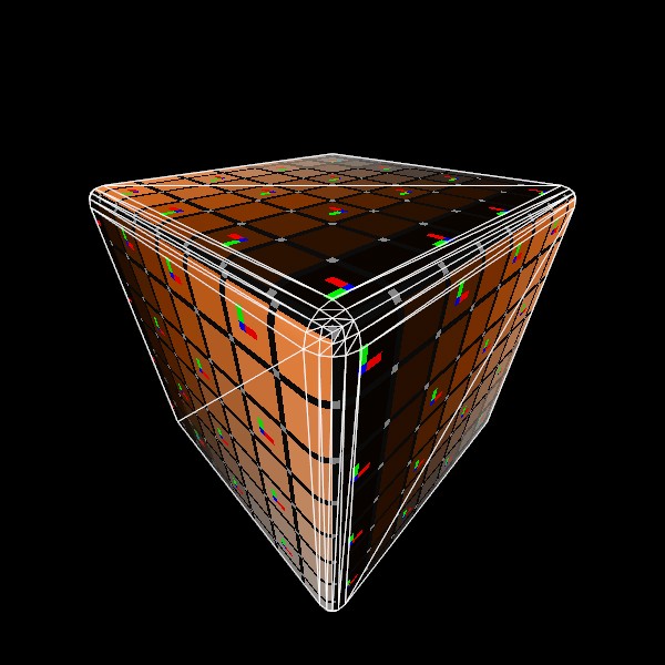
meshRoundedCube = Mesh.GenerateRoundedCube(Vec3.One, 0.05f);
Mesh.GenerateSphere
Generating a Mesh and Model
Here’s a quick example of generating a mesh! You can store it in just a Mesh, or you can attach it to a Model for easier rendering later on.
// Do this in your initialization
Mesh  sphereMesh  = Mesh.GenerateSphere(0.4f);
Model sphereModel = Model.FromMesh(sphereMesh, Default.Material);
Mesh.GenerateSphere
Drawing both a Mesh and a Model generated this way is reasonably simple, here’s a short example! For the Mesh, you’ll need to create your own material, we just loaded up the default Material here.
// Call this code every Step

Matrix sphereTransform = Matrix.T(0, .5f, 0);
sphereMesh.Draw(Default.Material, sphereTransform);

sphereTransform = Matrix.T(1, .5f, 0);
sphereModel.Draw(sphereTransform);
Mesh.GenerateSphere
UV and Face layout
Here’s a test image that illustrates how this mesh’s geometry is
laid out.
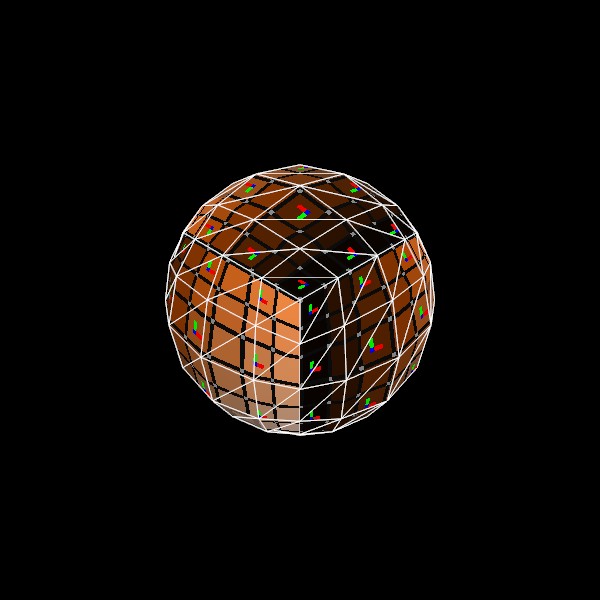
meshSphere = Mesh.GenerateSphere(1);
Mesh.Intersect
Ray Mesh Intersection
Here’s an example of casting a Ray at a mesh someplace in world space, transforming it into model space, calculating the intersection point, and displaying it back in world space.
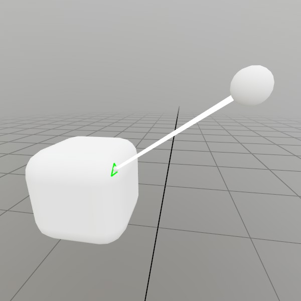
Mesh  sphereMesh = Default.MeshSphere;
Mesh  boxMesh    = Mesh.GenerateRoundedCube(Vec3.One*0.2f, 0.05f);
Pose  boxPose    = (Demo.contentPose * Matrix.T(0, -0.1f, 0)).Pose;
float boxScale   = 1;
Pose  castPose   = (Demo.contentPose * Matrix.T(0.25f, 0.11f, 0.2f)).Pose;

public void StepRayMesh()
{
	// Draw our setup, and make the visuals grab/moveable!
	UI.Handle("Box",  ref boxPose, boxMesh.Bounds, ref boxScale);
	UI.Handle("Cast", ref castPose, sphereMesh.Bounds*0.03f);
	boxMesh   .Draw(Default.MaterialUI, boxPose .ToMatrix(boxScale));
	sphereMesh.Draw(Default.MaterialUI, castPose.ToMatrix(0.03f));
	Lines.Add(castPose.position, boxPose.position, Color.White, 0.005f);

	// Create a ray that's in the Mesh's model space
	Matrix transform = boxPose.ToMatrix(boxScale);
	Ray    ray       = transform
		.Inverse
		.Transform(Ray.FromTo(castPose.position, boxPose.position));

	// Draw a sphere at the intersection point, if the ray intersects
	// with the mesh.
	if (ray.Intersect(boxMesh, Cull.Back, out Ray at, out uint index))
	{
		sphereMesh.Draw(Default.Material, Matrix.TS(transform.Transform(at.position), 0.01f));
		if (boxMesh.GetTriangle(index, out Vertex a, out Vertex b, out Vertex c))
		{
			Vec3 aPt = transform.Transform(a.pos);
			Vec3 bPt = transform.Transform(b.pos);
			Vec3 cPt = transform.Transform(c.pos);
			Lines.Add(aPt, bPt, new Color32(0,255,0,255), 0.005f);
			Lines.Add(bPt, cPt, new Color32(0,255,0,255), 0.005f);
			Lines.Add(cPt, aPt, new Color32(0,255,0,255), 0.005f);
		}
	}

}
Mesh.SetData
Procedurally generating a wavy grid
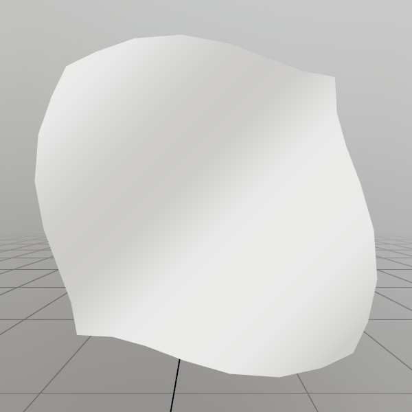
Here, we’ll generate a grid mesh using Mesh.SetVerts and Mesh.SetInds! This is a common example of creating a grid using code, we’re using a sin wave to make it more visually interesting, but you could also substitute this for something like sampling a heightmap, or a more interesting mathematical formula!
Note: x+y*gridSize is the formula for 2D (x,y) access of a 1D array that represents a grid.
const int   gridSize = 8;
const float gridMaxF = gridSize-1;
Vertex[] verts = new Vertex[gridSize*gridSize];
uint  [] inds  = new uint  [gridSize*gridSize*6];

for (int y = 0; y < gridSize; y++) {
for (int x = 0; x < gridSize; x++) {
	// Create a vertex on a grid, centered about the origin. The dimensions extends
	// from -0.5 to +0.5 on the X and Z axes. The Y value is then sampled from
	// a sin wave using the x and y values.
	//
	// The normal of the vertex is then calculated from the derivative of the Y
	// value!
	verts[x+y*gridSize] = new Vertex(
		new Vec3(
			x/gridMaxF-0.5f,
			SKMath.Sin((x+y) * 0.7f)*0.1f,
			y/gridMaxF-0.5f),
		new Vec3(
			-SKMath.Cos((x+y) * 0.7f),
			1,
			-SKMath.Cos((x+y) * 0.7f)).Normalized,
		new Vec2(
			x / gridMaxF,
			y / gridMaxF));

	// Create triangle face indices from the current vertex, and the vertices
	// on the next row and column! Since there is no 'next' row and column on
	// the last row and column, we guard this with a check for size-1.
	if (x<gridSize-1 && y<gridSize-1)
	{
		int ind = (x+y*gridSize)*6;
		inds[ind  ] = (uint)((x+1)+(y+1)*gridSize);
		inds[ind+1] = (uint)((x+1)+(y  )*gridSize);
		inds[ind+2] = (uint)((x  )+(y+1)*gridSize);

		inds[ind+3] = (uint)((x  )+(y+1)*gridSize);
		inds[ind+4] = (uint)((x+1)+(y  )*gridSize);
		inds[ind+5] = (uint)((x  )+(y  )*gridSize);
	}
} }
demoProcMesh = new Mesh(verts, inds);
Mesh.SetData
See Mesh.SetData
Mesh.SetInds
See Mesh.SetData
Mesh.SetVerts
See Mesh.SetData
Mesh.SetVerts
Custom vertex formats
Meshes can use custom vertex layouts! Define a struct that provides what your shader’s vertex stage needs, and tag each field with a VertComponent attribute saying what it is. StereoKit derives the vertex format from the struct automatically. Since vertex data is matched to shader inputs by semantic, fields don’t need to be in the same order as the shader declares them!
[StructLayout(LayoutKind.Sequential, Pack = 1)]
struct VertPosColor
{
	[VertComponent(VertSemantic.Color,    VertFmt.U8Normalized, 4)]
	public Color32 color;
	[VertComponent(VertSemantic.Position, VertFmt.F32,          3)]
	public Vec3    pos;

	public VertPosColor(Vec3 position, Color32 c) { pos = position; color = c; }
}

Mesh     _mesh;
Material _material;

Mesh BuildOctahedron(float s)
{
	Mesh mesh = new Mesh();
	mesh.SetVerts(new VertPosColor[] {
		new VertPosColor(V.XYZ( s, 0, 0), new Color32(255,  0,  0,255)),
		new VertPosColor(V.XYZ(-s, 0, 0), new Color32(  0,255,  0,255)),
		new VertPosColor(V.XYZ( 0, s, 0), new Color32(  0,  0,255,255)),
		new VertPosColor(V.XYZ( 0,-s, 0), new Color32(255,255,  0,255)),
		new VertPosColor(V.XYZ( 0, 0, s), new Color32(  0,255,255,255)),
		new VertPosColor(V.XYZ( 0, 0,-s), new Color32(255,  0,255,255)) });
	mesh.SetInds(new uint[] {
		2,4,0,  2,0,5,  2,5,1,  2,1,4,
		3,0,4,  3,5,0,  3,1,5,  3,4,1 });
	return mesh;
}
Mesh.SetVerts
See Mesh.SetData
Mesh.SetVerts
See Mesh.SetVerts
Mesh
See Mesh.Draw
Mesh
See Mesh.Draw
Microphone.IsRecording
Getting streaming sound intensity
This example shows how to read data from a Sound stream such as the microphone! In this case, we’re just finding the average ‘intensity’ of the audio, and returning it as a value approximately between 0 and 1. Microphone.Start() should be called before this example :)
float[] micBuffer    = new float[0];
float   micIntensity = 0;
float GetMicIntensity()
{
	if (!Microphone.IsRecording) return 0;

	// Ensure our buffer of samples is large enough to contain all the
	// data the mic has ready for us this frame
	if (Microphone.Sound.UnreadSamples > micBuffer.Length)
		micBuffer = new float[Microphone.Sound.UnreadSamples];

	// Read data from the microphone stream into our buffer, and track
	// how much was actually read. Since the mic data collection runs in
	// a separate thread, this will often be a little inconsistent. Some
	// frames will have nothing ready, and others may have a lot!
	int samples = Microphone.Sound.ReadSamples(ref micBuffer);

	// This is a cumulative moving average over the last 1000 samples! We
	// Abs() the samples since audio waveforms are half negative.
	for (int i = 0; i < samples; i++)
		micIntensity = (micIntensity*999.0f + Math.Abs(micBuffer[i]))/1000.0f;

	return micIntensity;
}
Microphone.Sound
See Microphone.IsRecording
Microphone.GetDevices
Choosing a microphone device
While generally you’ll prefer to use the default device, it can be nice to allow users to pick which mic they’re using! This is especially important on PC, where users may have complicated or interesting setups.
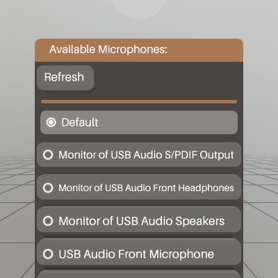
This sample is a very simple window that allows users to start recording with a device other than the default. NOTE: this example is designed with the assumption that Microphone.Start() has been called already.
Pose     micSelectPose   = new Pose(Demo.contentPose.Translation + V.XYZ(0,-0.12f,0), Demo.contentPose.Rotation);
string[] micDevices      = null;
string   micDeviceActive = null;
void ShowMicDeviceWindow()
{
	// Let the user choose a microphone device
	UI.WindowBegin("Available Microphones:", ref micSelectPose);

	// User may plug or unplug a mic device, so it's nice to be able to
	// refresh this list.
	if (UI.Button("Refresh") || micDevices == null)
		micDevices = Microphone.GetDevices();
	UI.HSeparator();

	// Display the list of potential microphones. Some systems may only
	// have the default (null) device available.
	Vec2 size = V.XY(0.25f, UI.LineHeight);
	if (UI.Radio("Default", micDeviceActive == null, size))
	{
		micDeviceActive = null;
		Microphone.Start(micDeviceActive);
	}
	foreach (string device in micDevices)
	{
		if (UI.Radio(device, micDeviceActive == device, size))
		{
			micDeviceActive = device;
			Microphone.Start(micDeviceActive);
		}
	}

	UI.WindowEnd();
}
Microphone.Start
See Microphone.GetDevices
Microphone.Start
Recording Audio Snippets
A common use case for the microphone would be to record a snippet of audio! This demo is a window that will read data from the Microphone, and use that to create a sound for playback.
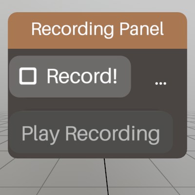
Sound       recordedSound   = null;
List<float> recordedData    = new List<float>();
float[]     sampleBuffer    = null;
bool        recording       = false;
Pose        recordingWindow = (Demo.contentPose * Matrix.T(-0.15f,0,0)).Pose;

void RecordAudio()
{
	UI.WindowBegin("Recording Panel", ref recordingWindow);

	// This code will begin a new recording, or finish an existing
	// recording!
	if (UI.Toggle("Record!", ref recording))
	{
		if (recording)
		{
			// Clear out our data, and start up the mic!
			recordedData.Clear();
			recording = Microphone.Start();
			if (!recording)
				Log.Warn("Recording failed to start!");
		}
		else
		{
			// Stop the mic, and pour our recorded samples into a new Sound
			Microphone.Stop();
			recordedSound = Sound.FromSamples(recordedData.ToArray());
		}
	}

	// If the mic is recording, every frame we'll want to grab all the data
	// from the Microphone's audio stream, and store it until we can make
	// a complete sound from it.
	if (Microphone.IsRecording)
	{
		if (sampleBuffer == null || sampleBuffer.Length < Microphone.Sound.UnreadSamples)
			sampleBuffer = new float[Microphone.Sound.UnreadSamples];
		int read = Microphone.Sound.ReadSamples(ref sampleBuffer);
		recordedData.AddRange(sampleBuffer[0..read]);
	}

	// Let the user know the current status of our recording code.
	UI.SameLine();
	if      (Microphone.IsRecording) UI.Label("recording...");
	else if (recordedSound != null)  UI.Label($"{recordedSound.Duration:0.#}s");
	else                             UI.Label("...");

	// If we have a recording, give the user a button that'll play it back!
	UI.PushEnabled(recordedSound != null);
	if (UI.Button("Play Recording"))
		recordedSound.Play(recordingWindow.position);
	UI.PopEnabled();

	UI.WindowEnd();
}
Microphone
See Microphone.IsRecording
Microphone
See Microphone.GetDevices
Microphone
See Microphone.Start
Model.ActiveAnim
See Anim.Name
Model.AnimCompletion
See Anim.Name
Model.AnimMode
See Anim.Name
Model.Anims
See Anim.Duration
Model.AnimTime
See Anim.Name
Model.Nodes
Simple iteration
Walking through the Model’s list of nodes is pretty straightforward! This will touch every ModelNode in the Model, in the order they were defined, regardless of hierarchy position or contents.
Log.Info("Iterate nodes:");
foreach (ModelNode node in model.Nodes)
	Log.Info($"  {node.Name}");
Model.Nodes
Tagged Nodes
You can search through Visuals and Nodes for nodes with some sort of tag in their names. Since these names are from your modeling software, this can allow for some level of designer configuration that can be specific to your project.
var nodes = model.Visuals
	.Where(n => n.Name.Contains("[Wire]"));
foreach (ModelNode node in nodes)
{
	node.Material = node.Material.Copy();
	node.Material.Wireframe = true;
}
Model.Nodes
Collision Tagged Nodes
One particularly practical example of tagging your ModelNode names would be to set up collision information for your Model. If, for example, you have a low resolution mesh designed specifically for fast collision detection, you can tag your non-solid nodes as “[Intangible]”, and your collider nodes as “[Invisible]”:
foreach (ModelNode node in model.Nodes)
{
	node.Solid   = node.Name.Contains("[Intangible]") == false;
	node.Visible = node.Name.Contains("[Invisible]")  == false;
}
Model.RootNode
Non-recursive depth first node traversal
If you need to walk through a Model’s node hierarchy, this is a method of doing this without recursion! You essentially do this by walking the tree down (Child) and to the right (Sibling), and if neither is present, then walking back up (Parent) until it can keep going right (Sibling) and then down (Child) again.
static void DepthFirstTraversal(Model model)
{
	ModelNode node  = model.RootNode;
	int       depth = 0;
	while (node != null)
	{
		string tabs = new string(' ', depth*2);
		Log.Info(tabs + node.Name);

		if      (node.Child   != null) { node = node.Child; depth++; }
		else if (node.Sibling != null)   node = node.Sibling;
		else {
			while (node != null)
			{
				if (node.Sibling != null) {
					node = node.Sibling;
					break;
				}
				depth--;
				node = node.Parent;
			}
		}
	}
}
Model.Visuals
See Mesh.IndCount
Model.Visuals
Simple iteration of visual nodes
This will iterate through every ModelNode in the Model with visual data attached to it!
Log.Info("Iterate visuals:");
foreach (ModelNode node in model.Visuals)
	Log.Info($"  {node.Name}");
Model.Visuals
See Model.Nodes
Model.Model
Model model = new Model();
model.AddNode("Cube",
	Matrix .Identity,
	Mesh   .GenerateCube(Vec3.One),
	Default.Material);
Model.AddNode
Assembling a Model
While normally you’ll load Models from file, you can also assemble them yourself procedurally! This example shows assembling a simple hierarchy of visual and empty nodes.
Model model = new Model();
model
	.AddNode ("Root",    Matrix.S(0.2f), Mesh.Cube, Material.Default)
	.AddChild("Sub",     Matrix.TR (V.XYZ(0.5f, 0, 0), Quat.FromAngles(0, 0, 45)), Mesh.Cube, Material.Default)
	.AddChild("Surface", Matrix.TRS(V.XYZ(0.5f, 0, 0), Quat.LookDir(V.XYZ(1,0,0)), V.XYZ(1,1,1)));

ModelNode surfaceNode = model.FindNode("Surface");

surfaceNode.AddChild("UnitX", Matrix.T(Vec3.UnitX));
surfaceNode.AddChild("UnitY", Matrix.T(Vec3.UnitY));
surfaceNode.AddChild("UnitZ", Matrix.T(Vec3.UnitZ));
Model.Copy
See Material.Copy
Model.FindAnim
See Anim.Duration
Model.FindNode
See Model.AddNode
Model.FromFile
See Anim.Duration
Model.FromFile
See Bounds
Model.PlayAnim
See Anim.Duration
Model
See Anim.Duration
Model
See Anim.Name
Model
See Bounds
Model
See Mesh.IndCount
Model
See Model.AddNode
Model
See Model.Nodes
Model
See Model.Visuals
Model
See Model.Nodes
Model
See Model.Nodes
Model
See Model.RootNode
Model
Recursive depth first node traversal
Recursive depth first traversal is a little simpler to implement as
long as you don’t mind some recursion :)
This would be called like: RecursiveTraversal(model.RootNode);
static void RecursiveTraversal(ModelNode node, int depth = 0)
{
	string tabs = new string(' ', depth*2);
	while (node != null)
	{
		Log.Info(tabs + node.Name);
		RecursiveTraversal(node.Child, depth + 1);
		node = node.Sibling;
	}
}
ModelNode.Child
See Model.RootNode
ModelNode.Child
See Model
ModelNode.Info
Modifying ModelNode.Info
While ModelNode.Info is automatically populated from a GLTF’s “extras”, you can also embed or modify with your own data as well.
ModelNode modelNode = model.AddNode("empty", Matrix.Identity);
modelNode.Info.Add("a", "1");
modelNode.Info.Add("b", "2");
modelNode.Info.Add("c", "3");
modelNode.Info.Add("c", "10"); // overwrite 'c's value
modelNode.Info.Remove("b");
ModelNode.Info
Iterating through ModelNode.Info
You can choose to iterate through different parts of ModelNode.Info using foreach loops.
foreach (ModelNode node in model.Nodes)
{
	foreach (KeyValuePair<string, string> kvp in node.Info)
		Log.Info($"{kvp.Key} - {kvp.Value}");

	foreach (string key in node.Info.Keys)
		Log.Info($"key: {key} - {node.Info[key]}");

	foreach (string val in node.Info.Values)
		Log.Info($"value: {val}");
}
ModelNode.Material
foreach (ModelNode node in model.Nodes)
{
	// ModelNode.Material will often returned a shared resource, so
	// copy it if you don't wish to change all assets that share it.
	Material mat = node.Material.Copy();
	mat[MatParamName.ColorTint] = Color.HSV(0, 1, 1);
	node.Material = mat;
}
ModelNode.Parent
See Model.RootNode
ModelNode.Parent
See Model
ModelNode.Sibling
See Model.RootNode
ModelNode.Sibling
See Model
ModelNode.Solid
See Model.Nodes
ModelNode.Visible
See Model.Nodes
ModelNode.AddChild
See Model.AddNode
ModelNodeInfoCollection.Keys
See ModelNode.Info
ModelNodeInfoCollection.Values
See ModelNode.Info
ModelNodeInfoCollection.Add
See ModelNode.Info
ModelNodeInfoCollection.Remove
See ModelNode.Info
OcclusionCaps
Basic World Occlusion
A simple example of turning on occlusion. The method you use depends
on what the device supports — check World.OcclusionCapabilities to
see what’s available. For example, HoloLens supports
OcclusionCaps.Mesh, while Quest supports OcclusionCaps.Depth.
OcclusionCaps prevOcclusion;

public void Start()
{
	OcclusionCaps available = World.OcclusionCapabilities;
	if (available == OcclusionCaps.None)
		Log.Info("Occlusion not available!");

	// Store current state so we can restore it later
	prevOcclusion = World.Occlusion;

	// Enable whatever occlusion the device supports
	World.Occlusion = available;
}

public void Stop()
{
	// Restore the previous occlusion state
	World.Occlusion = prevOcclusion;
}
Platform.FilePickerVisible
Opening a Model
This is a simple button that will open a 3D model selection file picker, and make a call to OnLoadModel after a file has been successfully picked!
if (UI.Button("Open Model") && !Platform.FilePickerVisible) {
	Platform.FilePicker(PickerMode.Open, OnLoadModel, null, Assets.ModelFormats);
}
Platform.FilePickerVisible
Once you have the filename, it’s simply a matter of loading it from file. This is an example of async loading a model, and calculating a scale value that ensures the model is a reasonable size.
private void OnLoadModel(string filename)
{
	model          = Model.FromFile(filename);
	modelTask      = Assets.CurrentTask;
	modelScale     = 1;
	modelScaleDone = false;
	model.OnLoaded += (m) => {
		if (m.Anims.Count > 0)
			m.PlayAnim(m.Anims[0], AnimMode.Loop);
	};
}
Platform.FilePicker
See Platform.FilePickerVisible
Platform.FilePicker
See Platform.FilePickerVisible
Platform.FilePicker
Read Custom Files
Platform.FilePicker(PickerMode.Open, file => {
	// On some platforms, using StereoKit's Platform.ReadFile
	// instead of C#'s File IO functions may help bypass permission
	// issues.
	if (Platform.ReadFile(file, out string text))
		Log.Info(text);
}, null, ".txt");
Platform.FilePicker
Write Custom Files
Platform.FilePicker(PickerMode.Save, file => {
	// On some platforms, using StereoKit's Platform.WriteFile
	// instead of C#'s File IO functions may help bypass permission
	// issues.
	Platform.WriteFile(file, "Text for the file.\n- Thanks!");
}, null, ".txt");
Platform.ReadFile
See Platform.FilePicker
Platform.WriteFile
See Platform.FilePicker
Pose.Forward
Pose Directions
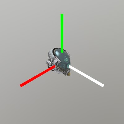
Pose provides a few handy vector properties to help working with
Pose relative directions! Forward, Right, and Up are all
derived from the Pose’s orientation, and represent the -Z, +X and
+Y directions of the Pose.
Pose p = new Pose(0,0,-0.5f);
model.Draw(p.ToMatrix(0.03f));

Lines.Add(p.position, p.position + 0.1f*p.Right,   new Color32(255,0,0,255), 0.005f);
Lines.Add(p.position, p.position + 0.1f*p.Up,      new Color32(0,255,0,255), 0.005f);
Lines.Add(p.position, p.position + 0.1f*p.Forward, Color32.White,            0.005f);
Pose.Identity
See Lines.AddAxis
Pose.Right
See Pose.Forward
Pose.Up
See Pose.Forward
Pose.Pose
Lerping Poses

Here we construct two Poses, one using a position + direction
constructor, and one using a from -> to LookAt function. Both are
valid ways of constructing a Pose, check out the Quat
functions for more tools for creating Pose orientations!
After that, we’re just blending between these two Poses with a
Pose.Lerp, and showing the result at 10% intervals.
Pose a = new Pose(0, 0.5f, -0.5f, Quat.LookDir(1,0,0));
Pose b = Pose.LookAt(V.XYZ(0,0,0), V.XYZ(0,1,0));

for (int i = 0; i < 11; i++) {
	Pose p = Pose.Lerp(a, b, i/10.0f);
	Lines.AddAxis(p, 0.05f);
}

// Show the origin for clarity
Lines.Add(V.XYZ(-1,0,0), V.XYZ(1,0,0), new Color32(100,0,0,100), 0.0025f);
Lines.Add(V.XYZ(0,-1,0), V.XYZ(0,1,0), new Color32(0,100,0,100), 0.0025f);
Lines.Add(V.XYZ(0,0,-1), V.XYZ(0,0,1), new Color32(0,0,100,100), 0.0025f);
Pose.Lerp
See Pose.Pose
Pose.LookAt
See Pose.Pose
Pose.ToMatrix
Draw Pose
Having a raw and malleable position/orientation available is great,
but with Pose.ToMatrix, you can also quickly turn a Pose into a
Matrix for use with drawing functions or other places where
Matrix transforms are needed! ToMatrix also has overloads to
include a scale, if one is available.

Pose  pose  = new Pose(0,0,-0.5f, Quat.FromAngles(30,45,0));
float scale = 0.5f;

Mesh.Cube.Draw(Material.Default, pose.ToMatrix(scale));
Pose
See Lines.AddAxis
Pose
See Pose.Pose
Pose
See Pose.ToMatrix
Pose
See Pose.Forward
Projection
Toggling the projection mode
Only in flatscreen apps, there is the option to change the main camera’s projection mode between perspective and orthographic.
if (SK.ActiveDisplayMode == DisplayMode.Flatscreen &&
	Input.Key(Key.P).IsJustActive())
{
	Renderer.Projection = Renderer.Projection == Projection.Perspective
		? Projection.Ortho
		: Projection.Perspective;
}
Quat.Delta
Pose spherePose  = new Pose(-1, 0, 1, Quat.Identity);
Quat sphereDelta = Quat.Identity;
Vec3 oldPalmPos;
void SpinningSphere()
{
	// Draw a sphere that you can spin around with your right hand!
	Vec3 palmPos = Input.Hand(Handed.Right).palm.position - spherePose.position;
	if (palmPos.Length < 0.3f)
	{
		sphereDelta = Quat.Delta(oldPalmPos.Normalized, palmPos.Normalized);
	}
	spherePose.orientation = sphereDelta * spherePose.orientation;
	oldPalmPos = palmPos;
	Mesh.Sphere.Draw(matDev, spherePose.ToMatrix(0.5f));
}
Quat.LookAt
Quat.LookAt and LookDir are probably one of the easiest ways to work with quaternions in StereoKit! They’re handy functions to have a good understanding of. Here’s an example of how you might use them.
// Draw a box that always rotates to face the user
Vec3 boxPos = new Vec3(1,0,1);
Quat boxRot = Quat.LookAt(boxPos, Input.Head.position);
Mesh.Cube.Draw(Material.Default, Matrix.TR(boxPos, boxRot));

// Make a Window that faces a user that enters the app looking
// Forward.
Pose winPose = new Pose(0,0,-0.5f, Quat.LookDir(0,0,1));
UI.WindowBegin("Posed Window", ref winPose);
UI.WindowEnd();
Quat
See Quat.LookAt
Ray.Intersect
See Mesh.Intersect
Renderer.Projection
See Projection
Renderer.SkyLight
Setting lighting to an equirect cubemap
Changing the environment’s lighting based on an image is a really great way to instantly get a particular feel to your scene! A neat place to find compatible equirectangular images for this is Poly Haven
Renderer.SkyTex   = Tex.FromCubemap("old_depot.hdr");
Renderer.SkyLight = Renderer.SkyTex.CubemapLighting;
And here’s what it looks like applied to the default Material!
Renderer.SkyTex
See Renderer.SkyLight
Renderer.RenderTo
Rendering a viewpoint with post-processing
RenderSettings works with Renderer.RenderTo and RenderList.DrawNow, and can carry a post-process chain that applies to just that pass!
Tex target = Tex.RenderTarget(512, 512);
Renderer.RenderTo(target, Matrix.T(0, 0, 1), Matrix.Perspective(90, 1, 0.1f, 50),
	new RenderSettings { clearColor  = Color.Black,
	                     postProcess = new Material[] { vignette } });
Renderer.SetPostProcess
Setting a post-process chain
A post-process effect is just a Material! Its shader reads the scene through an input attachment named ‘color’, and its parameters can be changed live, like any other Material. The chain renders in argument order.
Material vignette = new Material("postfx_vignette.hlsl");
vignette["strength"] = 0.4f;
Renderer.SetPostProcess(vignette);
And when you’re done with it:
Renderer.SetPostProcess();
RenderList.Add
Render Icon From a Model
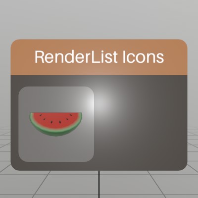
One place where RenderList excels, is at rendering icons or previews of Models or scenes! This snippet of code will take a Model asset, and render a preview of it into a small Sprite.
static Sprite MakeIcon(Model model, int resolution)
{
	RenderList list   = new RenderList();
	Tex        result = Tex.RenderTarget(resolution, resolution, 8);

	// Calculate a standard size that will fill the icon to the edges,
	// based on the camera parameters we pass to DrawNow.
	float scale = 1/model.Bounds.dimensions.Length;

	list.Add(model, Matrix.TS(-model.Bounds.center*scale, scale), Color.White);

	list.DrawNow(result,
		Matrix.LookAt(V.XYZ(0,0,-1), Vec3.Zero, Vec3.Up),
		Matrix.Perspective(45, 1, 0.01f, 10));

	// Clearing isn't _necessary_ here, but DrawNow does not clear the list
	// after drawing! This will free up assets that were referenced in the
	// list without waiting for GC to destroy the RenderList object.
	list.Clear();

	return Sprite.FromTex(result.Copy());
}
From there, it’s pretty easy to load a Model up, and draw it on a button in the UI.
Sprite icon;
public void Initialize()
{
	Model model = Model.FromFile("Watermelon.glb");
	// Model loading is async, so we want to make sure the Model is fully
	// loaded before comitting it to a Sprite!
	Assets.BlockForPriority(int.MaxValue);
	icon = MakeIcon(model, 128);
}

Pose windowPose = new Pose(0,0,-0.5f, Quat.LookDir(0,0,1));
void ShowWindow()
{
	UI.WindowBegin("RenderList Icons", ref windowPose);
	UI.ButtonImg("Icon", icon, UIBtnLayout.CenterNoText, V.XX(UI.LineHeight*2));
	UI.WindowEnd();
}
RenderList.DrawNow
See RenderList.Add
RenderList
See RenderList.Add
RenderSettings
See Renderer.RenderTo
SK.AppFocus
See AppFocus
Sound.UnreadSamples
See Microphone.IsRecording
Sound.FromFile
Basic usage
Sound sound = Sound.FromFile("BlipNoise.wav");
sound.Play(Vec3.Zero);
Sound.FromSamples
See Microphone.Start
Sound.FromSamples
Generating a sound via samples
Making a procedural sound is pretty straightforward! Here’s an example of building a 500ms sound from two frequencies of sin wave.
float[] samples = new float[(int)(48000*0.5f)];
for (int i = 0; i < samples.Length; i++)
{
	float t = i/48000.0f;
	float band1 = SKMath.Sin(t * 523.25f * SKMath.Tau); // a 'C' tone
	float band2 = SKMath.Sin(t * 659.25f * SKMath.Tau); // an 'E' tone
	const float volume = 0.1f;
	samples[i] = (band1 * 0.6f + band2 * 0.4f) * volume;
}
Sound sampleSound = Sound.FromSamples(samples);
sampleSound.Play(Vec3.Zero);
Sound.Generate
Generating a sound via generator
Making a procedural sound is pretty straightforward! Here’s an example of building a 500ms sound from two frequencies of sin wave.
Sound genSound = Sound.Generate((t) =>
{
	float band1 = SKMath.Sin(t * 523.25f * SKMath.Tau); // a 'C' tone
	float band2 = SKMath.Sin(t * 659.25f * SKMath.Tau); // an 'E' tone
	const float volume = 0.1f;
	return (band1*0.6f + band2*0.4f) * volume;
}, 0.5f);
genSound.Play(Vec3.Zero);
Sound.Play
See Sound.FromFile
Sound.ReadSamples
See Microphone.IsRecording
Sound.ReadSamples
See Microphone.Start
Sound
See Microphone.IsRecording
Sound
See Sound.FromFile
Sound
See Sound.Generate
Sound
See Sound.FromSamples
Sprite.FromTex
Generating Particle Sprites
Sometimes you just need a small blob of color for visual effects or other things! Instead of firing up an image editor, you can just use Tex.GenParticle!
This sample generates a number of different shapes defined by the
roundness parameter. Starting at 0, and increasing at .1
increments to 1.0.
Sprite[] sprites = new Sprite[10];
for (int i = 0; i < sprites.Length; i++)
{
	float roundness   = i / (float)(sprites.Length - 1);
	Tex   particleTex = Tex.GenParticle(64, 64, roundness);
	sprites[i] = Sprite.FromTex(particleTex, SpriteType.Single);
}
// :End:

spriteList = sprites;
	}


ublic void Step() {
Hierarchy.Push(Matrix.T(0,4,2));

Sprite[] sprites = spriteList;
:CodeSample: Tex.GenParticle Sprite.FromTex And here’s what that looks like when you draw using this code!
for (int i = 0; i < sprites.Length; i++)
	sprites[i].Draw(Matrix.TS(V.XY0(i%5, -i/5)*0.1f, 0.1f), Pivot.TopRight);

SystemInfo.worldRaycastPresent
Basic World Raycasting
World.RaycastEnabled must be true before calling World.Raycast, or you won’t ever intersect with any world geometry.
public void Start()
{
	if (!SK.System.worldRaycastPresent)
		Log.Info("World raycasting not available!");

	// This must be enabled before calling World.Raycast
	World.RaycastEnabled = true;
}

public void Stop() => World.RaycastEnabled = false;

public void StepRaycast()
{
	// Raycast out the index finger of each hand, and draw a red sphere
	// at the intersection point.
	for (int i = 0; i < 2; i++)
	{
		Hand hand = Input.Hand(i);
		if (!hand.IsTracked) continue;

		Ray fingerRay = hand[FingerId.Index, JointId.Tip].Pose.Ray;
		if (World.Raycast(fingerRay, out Ray at))
			Mesh.Sphere.Draw(Material.Default, Matrix.TS(at.position, 0.03f), new Color(1, 0, 0));
	}
}
Tex.FromCubemapEquirectangular
See Renderer.SkyLight
Tex.GenParticle
See Sprite.FromTex
Tex.GetColorData
Get data from a Tex
Reading texture data from a Tex can be a slow operation, since texture memory lives on the GPU, and isn’t generally optimized for readability. But, sometimes you still have to do it! Just remember to avoid doing it too often or casually, and be cautious about how you treat the large amounts of memory involved.
// Reading colors can be as simple as this! Remember to select a color
// format that matches the data stored in the texture, as StereoKit
// will not convert the data for you. Most images from file are 32 bit
// RGBA images!
Tex texture = Tex.FromFile("floor.png");
Color32[] colors = texture.GetColorData<Color32>();

// For a more complex texture, such as this generated texture with 32
// bits per channel, we can load the data into a float array, with 4
// floats per-pixel! A `Color` would probably be fine here too.
Tex texture2 = Tex.GenColor(Color.White, 16, 16, TexType.Image, TexFormat.Rgba128);
float[] colors2 = texture2.GetColorData<float>(0, 4);
Tex.SetColors
Creating a texture procedurally
It’s pretty easy to create an array of colors, and just pass that into an empty texture! Here, we’re building a simple grid texture, like so:
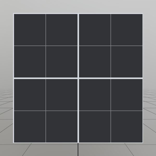
You can call SetTexture as many times as you like! If you’re calling it frequently, you may want to keep the width and height consistent to prevent from creating new texture objects. Use TexType.ImageNomips to prevent StereoKit from calculating mip-maps, which can be costly, especially when done frequently.
// Create an empty texture! This is TextType.Image, and
// an RGBA 32 bit color format.
Tex gridTex = new Tex();

// Use point sampling to ensure that the grid lines are
// crisp and sharp, not blended with the pixels around it.
gridTex.SampleMode = TexSample.Point;

// Allocate memory for the pixels we'll fill in, powers
// of two are always best for textures, since this makes
// things like generating mip-maps easier.
int width  = 128;
int height = 128;
Color32[] colors = new Color32[width*height];

// Create a color for the base of the grid, and the
// lines of the grid
Color32 baseColor    = Color.HSV(0.6f,0.1f,0.25f);
Color32 lineColor    = Color.HSV(0.6f,0.05f,1);
Color32 subLineColor = Color.HSV(0.6f,0.05f,.6f);

// Loop through each pixel
for (int y = 0; y < height; y++) {
for (int x = 0; x < width;  x++) {
	// If the pixel's x or y value is a multiple of 64, or
	// if it's adjacent to a multiple of 128, then we
	// choose the line color! Otherwise, we use the base.
	if (x % 128 == 0 || (x+1)%128 == 0 || (x-1)%128 == 0 ||
		y % 128 == 0 || (y+1)%128 == 0 || (y-1)%128 == 0)
		colors[x+y*width] = lineColor;
	else if (x % 64 == 0 || y % 64 == 0)
		colors[x+y*width] = subLineColor;
	else
		colors[x+y*width] = baseColor;
} }

// Put the pixel information into the texture
gridTex.SetColors(width, height, colors);
Text.Add
See Font.FromFile
Text.Add
See Font.FromFile
Text.Add
See Font.FromFile
Text.MakeStyle
See Font.FromFile
Text.MakeStyle
See Font.FromFile
Text.MakeStyle
See Font.FromFile
Text.SizeLayout
Text Sizes
When you need to work with placing text, Text.SizeLayout and
Text.SizeRender are the keys to the kingdom! SizeLayout will
give you the size of your text as far as layout is generally
concerned, while SizeRender will take your layout size and
provide the total bounds that you need to watch out for! Some fonts
can have absolutely unreasonable ascenders and descenders for
some of their glyphs. Extreme cases can be a bit rare, so in
general you’ll only need to work with the layout size. Just watch
out when you need to clip your text!
 You can see here with Segoe UI, the ascender area for rendering looks ridiculous.
In this screenshot, the black area represents the layout size, while the gray area represents the render size. “lÔTy” is a decent set of characters to illustrate a pretty normal range of height variation.
string text  = "lÔTy";
TextStyle style = TextStyle.Default;

Text.Add(text, Matrix.Identity, style, Pivot.Center);

// Calculate the text sizes! Layout size is used for placing text, but
// render size indicates the total area where text could end up,
// accounting for _extreme_ ascenders and descenders.
Vec2 layoutSz = Text.SizeLayout(text,     style);
Vec2 renderSz = Text.SizeRender(layoutSz, style, out float renderYOff);

// Draw the layout size behind the text in black
Mesh.Quad.Draw(Material.Unlit,
	Matrix.TS(V.XYZ(0, 0, 0.0001f), (-layoutSz).XY1),
	Color.Black);

// Draw the render size behind the text in gray, note that we're
// dividing the y offset by 2 because we're drawing from the _center_
// of a quad rather than something like the top left.
Mesh.Quad.Draw(Material.Unlit,
	Matrix.TS(V.XYZ(0, renderYOff/2.0f, 0.0002f), (-renderSz).XY1),
	new Color(0.2f,0.2f,0.2f));
Text.SizeRender
See Text.SizeLayout
TextStyle.Ascender
TextStyle Info
If you’re doing advanced text layout, StereoKit does provide some information about the font underlying the TextStyle! Here’s a quick sketch that shows what all that info represents:

// Some representative characters:
// l frequently goes above CapHeight all the way to the Ascender.
// Ô will go past the Ascender outside the layout bounds, and slightly below the baseline.
// T goes the whole way from Baseline to CapHeight.
// y will go all the way down to the descender.
string text = "lÔTy";

// Draw the text
Text.Add(text, Matrix.Identity, style, Pivot.TopLeft, Align.TopLeft);

// Show the bounding regions for the size of the text
Color colLayoutArea = new Color(0.1f,  0.1f, 0.1f);
Color colRenderArea = new Color(0.25f, 0.5f, 0.25f);

Vec2 size  = Text.SizeLayout(text, style);
Vec2 sizeR = Text.SizeRender(size, style, out float yOff);

Mesh.Quad.Draw(Material.Unlit, Matrix.TS(size .XY0/-2 + V.XYZ(0, 0,    0.0001f), size .XY1), colLayoutArea);
Mesh.Quad.Draw(Material.Unlit, Matrix.TS(sizeR.XY0/-2 + V.XYZ(0, yOff, 0.0002f), sizeR.XY1), colRenderArea);

// Show lines representing the typography units for this style
Color32 colCapHeight  = new Color32( 50, 255,  50, 255);
Color32 colBaseline   = new Color32(255, 255, 255, 255);
Color32 colAscender   = new Color32(255,  50,  50, 255);
Color32 colDescender  = new Color32( 50,  50, 255, 255);
Color32 colLineHeight = new Color32(255, 255, 255, 255);

float baselineAt   = -style.CapHeight;
float ascenderAt   = baselineAt + style.Ascender;
float capHeightAt  = baselineAt + style.CapHeight;
float descenderAt  = baselineAt - style.Descender;
float lineHeightAt = ascenderAt - style.LineHeightPct * style.TotalHeight;

Lines.Add(V.XY0(0, ascenderAt  ), V.XY0(-size.x, ascenderAt  ), colAscender,   0.003f);
Lines.Add(V.XY0(0, baselineAt  ), V.XY0(-size.x, baselineAt  ), colBaseline,   0.003f);
Lines.Add(V.XY0(0, capHeightAt ), V.XY0(-size.x, capHeightAt ), colCapHeight,  0.003f);
Lines.Add(V.XY0(0, descenderAt ), V.XY0(-size.x, descenderAt ), colDescender,  0.003f);
Lines.Add(V.XY0(0, lineHeightAt), V.XY0(-size.x, lineHeightAt), colLineHeight, 0.003f);
TextStyle.CapHeight
See TextStyle.Ascender
TextStyle.Descender
See TextStyle.Ascender
TextStyle.LineHeightPct
See TextStyle.Ascender
TextStyle.TotalHeight
See TextStyle.Ascender
TextStyle
See TextStyle.Ascender
TrackState
See Controller.aim
Transparency.Add
See Material.Transparency
Transparency.Blend
See Material.Transparency
Transparency.MSAA
See Material.Transparency
UI.Enabled
Enabling and Disabling UI Elements
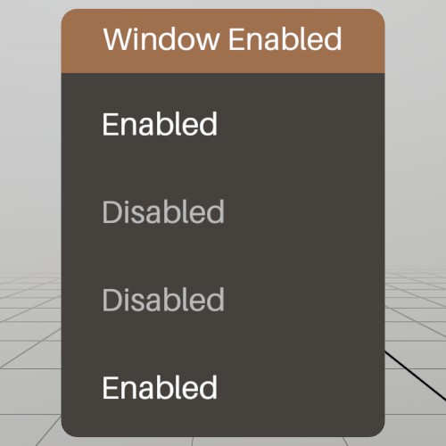
UI.Push/PopEnabled allows you to enable and disable groups of UI elements! This is a hierarchical stack, so by default, all PushEnabled calls inherit the stack’s state.
Pose windowPoseEnabled = new Pose(1.8f, 0, 0, Quat.Identity);
void ShowWindowEnabled()
{
	UI.WindowBegin("Window Enabled", ref windowPoseEnabled);

	// Default state of the enabled stack is true
	UI.Label(UI.Enabled ? "Enabled" : "Disabled");

	UI.PushEnabled(false);
	{
		// This label will be disabled
		UI.Label(UI.Enabled?"Enabled":"Disabled");

		UI.PushEnabled(true);
		{
			// This label inherits the state of the parent, so is therefore
			// disabled
			UI.Label(UI.Enabled?"Enabled":"Disabled");
		}
		UI.PopEnabled();

		UI.PushEnabled(true, HierarchyParent.Ignore);
		{
			// This label was enabled, overriding the parent, and so is
			// enabled.
			UI.Label(UI.Enabled ? "Enabled" : "Disabled");
		}
		UI.PopEnabled();
	}
	UI.PopEnabled();

	UI.WindowEnd();
}
UI.LastElementActive
Checking UI element status
It can sometimes be nice to know how the user is interacting with a particular UI element! The UI.LastElementX functions can be used to query a bit of this information, but only for the most recent UI element that uses an id!
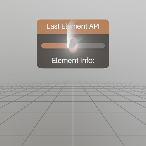
So in this example, we’re querying the information for the “Slider” UI element. Note that UI.Text does NOT use an id, which is why this works.
UI.WindowBegin("Last Element API", ref windowPose);

UI.HSlider("Slider", ref sliderVal, 0, 1, 0.1f, 0, UIConfirm.Pinch);
UI.Text("Element Info:", Align.TopCenter);
if (UI.LastElementSourceActive (InteractorSource.HandLeft  | InteractorSource.ControllerLeft ).IsActive()) UI.Label("Left Active");
if (UI.LastElementSourceActive (InteractorSource.HandRight | InteractorSource.ControllerRight).IsActive()) UI.Label("Right Active");
if (UI.LastElementSourceFocused(InteractorSource.HandLeft  | InteractorSource.ControllerLeft ).IsActive()) UI.Label("Left Focused");
if (UI.LastElementSourceFocused(InteractorSource.HandRight | InteractorSource.ControllerRight).IsActive()) UI.Label("Right Focused");
if (UI.LastElementFocused.IsActive()) UI.Label("Focused");
if (UI.LastElementActive .IsActive()) UI.Label("Active");

UI.WindowEnd();
UI.LastElementFocused
See UI.LastElementActive
UI.Button
A simple button
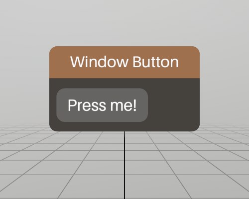
This is a complete window with a simple button on it! UI.Button
returns true only for the very first frame the button is pressed, so
using the if(UI.Button()) pattern works very well for executing
code on button press!
Pose windowPoseButton = new Pose(0, 0, 0, Quat.Identity);
void ShowWindowButton()
{
	UI.WindowBegin("Window Button", ref windowPoseButton);

	if (UI.Button("Press me!"))
		Log.Info("Button was pressed.");

	UI.WindowEnd();
}
UI.HandleBegin
See Bounds
UI.HandleEnd
See Bounds
UI.HSeparator
Separating UI Visually

A separator is a simple visual element that fills the window horizontally. It’s nothing complicated, but can help create visual association between groups of UI elements.
Pose windowPoseSeparator = new Pose(.6f, 0, 0, Quat.Identity);
void ShowWindowSeparator()
{
	UI.WindowBegin("Window Separator", ref windowPoseSeparator, UIWin.Body);

	UI.Label("Content Header");
	UI.HSeparator();
	UI.Text("A separator can go a long way towards making your content "
	      + "easier to look at!", Align.TopCenter);

	UI.WindowEnd();
}
UI.HSlider
Horizontal Sliders
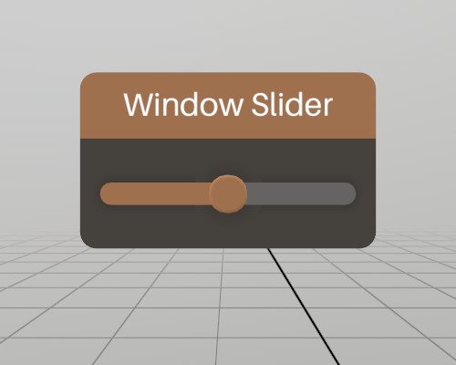
A slider will slide between two values at increments. The function requires a reference to a float variable where the slider’s state is stored. This allows you to manage the state yourself, and it’s completely valid for you to change the slider state separately, the UI element will update to match.
Note that UI.HSlider returns true only when the slider state has
changed, and does not return the current state.
Pose  windowPoseSlider = new Pose(.9f, 0, 0, Quat.Identity);
float sliderState      = 0.5f;
void ShowWindowSlider()
{
	UI.WindowBegin("Window Slider", ref windowPoseSlider);

	if (UI.HSlider("Slider", ref sliderState, 0, 1, 0.1f))
		Log.Info($"Slider value just changed: {sliderState}");

	UI.WindowEnd();
}
UI.Input
Text Input
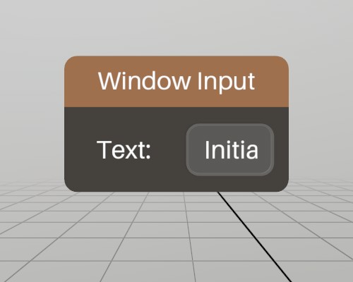
The UI.Input element allows users to enter text. Upon selecting the
element, a virtual keyboard will appear on platforms that provide
one. The function requires a reference to a string variable where
the input’s state is stored. This allows you to manage the state
yourself, and it’s completely valid for you to change the input state
separately, the UI element will update to match.
UI.Input will return true on frames where the text has just
changed.
Pose   windowPoseInput = new Pose(1.2f, 0, 0, Quat.Identity);
string inputState      = "Initial text";
void ShowWindowInput()
{
	UI.WindowBegin("Window Input", ref windowPoseInput);

	// Add a small label in front of it on the same line
	UI.Label("Text:");
	UI.SameLine();
	if (UI.Input("Text", ref inputState))
		Log.Info($"Input text just changed");

	UI.WindowEnd();
}
UI.Label
See UI.HSeparator
UI.LastElementSourceActive
See UI.LastElementActive
UI.LastElementSourceFocused
See UI.LastElementActive
UI.PopEnabled
See UI.Enabled
UI.PushEnabled
See UI.Enabled
UI.Radio
Radio button group
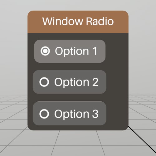
Radio buttons are a variety of Toggle button that behaves in a manner more conducive to radio group style behavior. This is an example of how to implement a small radio button group.
Pose windowPoseRadio = new Pose(1.5f, 0, 0, Quat.Identity);
int  radioState      = 1;
void ShowWindowRadio()
{
	UI.WindowBegin("Window Radio", ref windowPoseRadio);

	if (UI.Radio("Option 1", radioState == 1)) radioState = 1;
	if (UI.Radio("Option 2", radioState == 2)) radioState = 2;
	if (UI.Radio("Option 3", radioState == 3)) radioState = 3;

	UI.WindowEnd();
}
UI.SameLine
See UI.Input
UI.Text
See UI.HSeparator
UI.Text
Scrolling Text
UI.Text has an optional overload that allows you to scroll long
chunks of text! Here’s a simple example that allows you to scroll some
Lorem Ipsum text vertically.

Pose windowPoseScroll = new Pose(2.1f, 0, 0, Quat.Identity);
Vec2 scroll           = V.XY(0,0.1f);
void ShowWindowTextScroll()
{
	UI.WindowBegin("Window Text Scroll", ref windowPoseScroll);

	UI.Text(loremIpsum, ref scroll, UIScroll.Vertical, 0.1f);

	UI.WindowEnd();
}
UI.Toggle
A toggle button
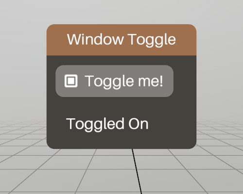
Toggle buttons swap between true and false when you press them! The function requires a reference to a bool variable where the toggle’s state is stored. This allows you to manage the state yourself, and it’s completely valid for you to change the toggle state separately, the UI element will update to match.
Note that UI.Toggle returns true only when the toggle state has
changed, and does not return the current state.
Pose windowPoseToggle = new Pose(.3f, 0, 0, Quat.Identity);
bool toggleState      = true;
void ShowWindowToggle()
{
	UI.WindowBegin("Window Toggle", ref windowPoseToggle);

	if (UI.Toggle("Toggle me!", ref toggleState))
		Log.Info("Toggle just changed.");
	if (toggleState) UI.Label("Toggled On");
	else             UI.Label("Toggled Off");

	UI.WindowEnd();
}
UI.VolumeAt
A volume is a 3D space that can be interacted with by any interactor, such as a hand, controller, or mouse pointer. This code draws an axis at the interactor’s location when it pinches while inside the VolumeAt.
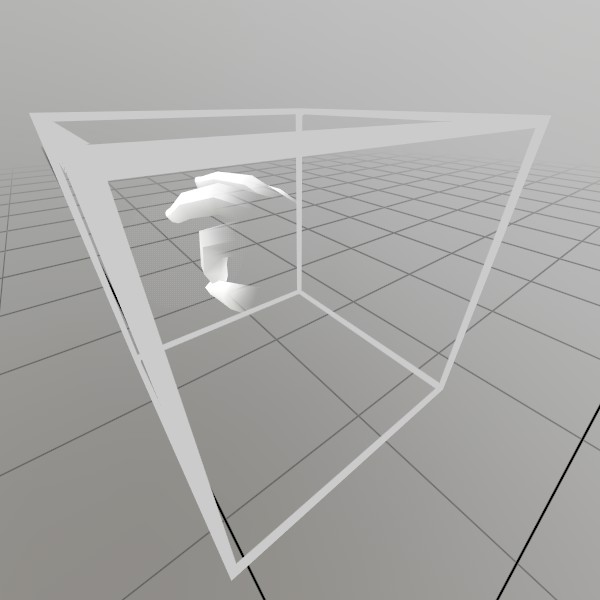
// Draw a transparent volume so the user can see this space
Vec3  volumeAt   = new Vec3(0, 0.2f, -0.4f);
float volumeSize = 0.2f;
Default.MeshCube.Draw(Default.MaterialUIBox, Matrix.TS(volumeAt, volumeSize));

BtnState volumeState = UI.VolumeAt("Volume", new Bounds(volumeAt, Vec3.One * volumeSize), UIConfirm.Pinch, out Interactor interactor);
if (volumeState != BtnState.Inactive)
{
	// If it just changed interaction state, make it jump in size
	float scale = volumeState.IsChanged()
		? 0.1f
		: 0.05f;
	Lines.AddAxis(interactor.Motion, scale);
}
UI.WindowBegin
See UI.Button
UI.WindowEnd
See UI.Button
UI
See UI.Button
UIWin
See UI.HSeparator
Vec2.Angle
Vec2 point = new Vec2(1, 0);
float angle0 = point.Angle();

point = new Vec2(0, 1);
float angle90 = point.Angle();

point = new Vec2(-1, 0);
float angle180 = point.Angle();

point = new Vec2(0, -1);
float angle270 = point.Angle();
Vec2.AngleBetween
Vec2 directionA = new Vec2( 1, 1);
Vec2 directionB = new Vec2(-1, 1);
float angle90 = Vec2.AngleBetween(directionA, directionB);

directionA = new Vec2(1, 1);
directionB = new Vec2(0,-2);
float angleNegative135 = Vec2.AngleBetween(directionA, directionB);
Vec3.Distance
Distance between two points
Distance does use a Sqrt call, so only use it if you definitely need the actual distance. Otherwise, consider DistanceSq.
Vec3  pointA   = new Vec3(3,2,5);
Vec3  pointB   = new Vec3(3,2,8);
float distance = Vec3.Distance(pointA, pointB);
Vec3.DistanceSq
Vec3 pointA = new Vec3(3, 2, 5);
Vec3 pointB = new Vec3(3, 2, 8);

float distanceSquared = Vec3.DistanceSq(pointA, pointB);
if (distanceSquared < 4*4) {
	Log.Info("Distance is less than 4");
}
VertComponentAttribute
See Mesh.SetVerts
VertFmt
See Mesh.SetVerts
VertSemantic
See Mesh.SetVerts
World.BoundsPose
// Here's some quick and dirty lines for the play boundary rectangle!
if (World.HasBounds)
{
	Vec2   s    = World.BoundsSize/2;
	Matrix pose = World.BoundsPose.ToMatrix();
	Vec3   tl   = pose.Transform( new Vec3( s.x, 0,  s.y) );
	Vec3   br   = pose.Transform( new Vec3(-s.x, 0, -s.y) );
	Vec3   tr   = pose.Transform( new Vec3(-s.x, 0,  s.y) );
	Vec3   bl   = pose.Transform( new Vec3( s.x, 0, -s.y) );

	Lines.Add(tl, tr, Color.White, 1.5f*U.cm);
	Lines.Add(bl, br, Color.White, 1.5f*U.cm);
	Lines.Add(tl, bl, Color.White, 1.5f*U.cm);
	Lines.Add(tr, br, Color.White, 1.5f*U.cm);
}
World.BoundsSize
See World.BoundsPose
World.HasBounds
See World.BoundsPose
World.Occlusion
See OcclusionCaps
World.Occlusion
Configuring Quality Occlusion
If you expect the user’s environment to change a lot, or you anticipate the user’s environment may not be well scanned already, then you may wish to boost the frequency of world data updates. By default, StereoKit is quite conservative about scanning to reduce computation, but this can be configured using the World.RefreshX properties as seen here.
// If occlusion is not available, the rest of the code will have no
// effect.
if (World.OcclusionCapabilities == OcclusionCaps.None)
	Log.Info("Occlusion not available!");

// Configure SK to update the world data as fast as possible, this
// allows occlusion to accomodate better for moving objects.
World.Occlusion       = World.OcclusionCapabilities;
World.RefreshType     = WorldRefresh.Timer; // Refresh on a timer
World.RefreshInterval = 0; // Refresh every 0 seconds
World.RefreshRadius   = 6; // Get everything in a 6m radius
World.OcclusionCapabilities
See OcclusionCaps
World.OcclusionCapabilities
See World.Occlusion
World.RaycastEnabled
See SystemInfo.worldRaycastPresent
World.RefreshInterval
See World.Occlusion
World.RefreshRadius
See World.Occlusion
World.RefreshType
See World.Occlusion
World.Raycast
See SystemInfo.worldRaycastPresent
World
See World.Occlusion
WorldRefresh
See World.Occlusion
Ease
Easing a Cube
Here we’re just animating a cube around, using some custom easing functions as well as builtin ones! The color here is animated using a conventional animation, just flipping through various hues, but the pose and scale are using easing to go to a position and come back!
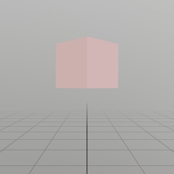
// Initial starting values for the pose, size, and color of a cube that
// we'll animate!
EasePose  pose  = new EasePose (V.XYZ(0,-0.1f,-0.5f), Quat.Identity);
EaseVec3  scale = new EaseVec3 (0.1f,0.1f,0.1f);
EaseColor color = new EaseColor(Color.White);

// Here's a custom easing function! This one goes from 0 to 1 and then back
// to 0 again! So it actually ends in the exact same place it started. We
// could achieve the same behavior with just sin(pi*t), but the rest of the
// math here softens the start and end of the animation.
// See a graph here: https://www.desmos.com/calculator/zz8cdvrvju
static float EaseReturn(float t) => (float)Math.Sin(2*Math.PI*t - 0.5*Math.PI) * 0.5f + 0.5f;

void StepEasedCube()
{
	// If the Ease animation for the Pose is finished or never started to
	// begin with, we can make it hop with our custom `EaseReturn`
	// function!
	if (pose.IsFinished)
		pose.AnimTo(
			new Pose(V.XYZ(0, 0.1f, -0.5f), Quat.FromAngles(0, 180, 0)),
			0.5f,
			EaseReturn);

	if (scale.IsFinished)
		scale.AnimTo(
			V.XYZ(0.15f, 0.15f, 0.15f),
			0.75f,
			EaseReturn);

	// For the color, we're picking a semi-random hue, and using one of the
	// built-in easing functions to just ease all the way to our
	// destination color!
	if (color.IsFinished)
		color.AnimTo(
			Color.HSV((Time.Frame % 100) / 100.0f, 0.7f, 0.7f),
			1,
			Ease.FastIn);

	// Convert `pose` and `scale` into a transform Matrix! Ease values have
	// implicit conversions that will automatically `Resolve` the current
	// value, so most of the time you can just pass them the same way you
	// would a normal type. In this case to call `ToMatrix` we need to
	// either explicitly cast, or call `Resolve`, and `Resolve` is the most
	// obvious action.
	Matrix transform = pose.Resolve().ToMatrix(scale);
	Mesh.Cube.Draw(Material.Default, transform, color);
}
EaseColor.IsFinished
See Ease
EaseColor.AnimTo
See Ease
EaseColor.Resolve
See Ease
EaseColor
See Ease
EasePose.IsFinished
See Ease
EasePose.AnimTo
See Ease
EasePose.Resolve
See Ease
EasePose
See Ease
EaseVec3.IsFinished
See Ease
EaseVec3.AnimTo
See Ease
EaseVec3.Resolve
See Ease
EaseVec3
See Ease
HandMenuItem
Basic layered hand menu
The HandMenuRadial is an IStepper, so it should be registered with
StereoKitApp.AddStepper so it can run by itself! It’s recommended to
keep track of it anyway, so you can remove it when you’re done with it
via StereoKitApp.RemoveStepper
The constructor uses a params style argument list that makes it easy and clean to provide lists of items! This means you can assemble the whole menu on a single ‘line’. You can still pass arrays instead if you prefer that!
handMenu = SK.AddStepper(new HandMenuRadial(
	new HandRadialLayer("Root",
		new HandMenuItem("File",   null, null, "File"),
		new HandMenuItem("Search", null, null, "Edit"),
		new HandMenuItem("About",  Sprite.FromFile("search.png"), () => Log.Info(SK.VersionName)),
		new HandMenuItem("Cancel", null, null)),
	new HandRadialLayer("File",
		new HandMenuItem("New",    null, () => Log.Info("New")),
		new HandMenuItem("Open",   null, () => Log.Info("Open")),
		new HandMenuItem("Close",  null, () => Log.Info("Close")),
		new HandMenuItem("Back",   null, null, HandMenuAction.Back)),
	new HandRadialLayer("Edit",
		new HandMenuItem("Copy",   null, () => Log.Info("Copy")),
		new HandMenuItem("Paste",  null, () => Log.Info("Paste")),
		new HandMenuItem("Back",   null, null, HandMenuAction.Back))));
HandMenuItem
SK.RemoveStepper(handMenu);
HandMenuRadial
See HandMenuItem
HandMenuRadial
See HandMenuItem
HandRadialLayer
See HandMenuItem
HandRadialLayer
See HandMenuItem
IStepper
See Backend.XRType
IStepper
See Backend.Graphics